Short answer: Lightning protection equipment covers every part that captures a strike, carries its current down and disperses it into the ground: an air rod or ESE air terminal and its base, copper tape or conductor, clamps, a disconnector (test joint), an earth rod and its clamp, an earth inspection pit, an earth bar and SPDs. These parts have to withstand lightning current and years of wind, rain and corrosion without loosening or decaying, which is why a dedicated standard, IEC 62561, sets tests for them.
To see how these components work together as a system, read our article on the lightning protection system and its components. This one is written from the buyer's point of view: what each part is, where it is installed, what it should be made of and what to check when you buy it. At KALOT Group we offer every part in this guide, and each name links to its product page.
Why not just any metal part will do in a lightning protection system
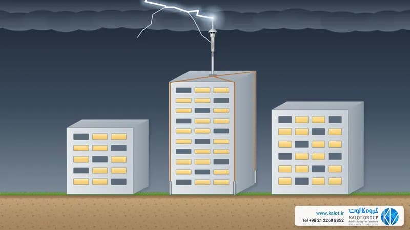
A lightning strike sends tens of thousands of amps through the system in less than a thousandth of a second. That current does three things to the parts: it heats them, it causes sparking at the joints, and its magnetic force shakes the conductors and pulls them out of their clamps. After that, the parts spend years under sun and rain, in polluted air and in damp soil. A clamp with a rusted bolt or a tape that has decayed in the soil will fail on the day of the strike, and nobody will notice until then.
That is why the design standard IEC 62305-3 sets the material and dimensions of conductors, while the IEC 62561 series defines specific tests for the parts themselves: after exposure to salt mist and polluted air, a part has to carry lightning current and remain sound. Before this series, the European reference for these parts was the EN 50164 series, and some catalogues still mention it.
Lightning protection equipment list, from roof to ground
The figure above shows a building with twelve main parts. Below we explain each group separately and tell you what to look at when choosing.
1. Air termination: air rods, ESE air terminals and bases
The air termination is the part the lightning strikes. There are two common types:
- Conventional air rod: a metal air rod installed on the roof, parapet edge, chimney or roof ridge, usually together with roof conductors (a mesh). We offer conventional air rods in solid copper, nickel-chrome plated copper and stainless steel, along with a three-pronged air rod tip.
- ESE air terminal: a head mounted on a mast that covers a wide area under the French standard NF C 17-102. Its tip must be at least 2 m above anything on the roof. We offer the ACTIVE 1D+, ACTIVE 2D and ACTIVE 4D ESE air terminals, with a telescopic mast, arched clamp and remote tester. We explain how to choose between the two methods in choosing the best lightning protection.
Bases hold the air rod on the surface and connect the conductor to it. A base must be made for that particular surface: brass base for flat roofs, roof ridge base, wall support, adjustable stainless steel base for flat and pitched roofs, and the couplings for connecting tape to the air rod and connecting conductor to the air rod. You can see them all under air rod bases.
What to check when buying: the air rod and base material must suit the conductor (for example a copper air rod with a brass base and copper tape), the air rod and base threads must match, and in windy locations the length and support of the air rod must be chosen accordingly.
2. Conductors: roof tape and conductor, and down conductors
The conductor carries the current from the air termination to the ground. Under IEC 62305-3, the cross-section of roof and down conductors must be at least 50 mm² for copper, galvanised steel and stainless steel, and 70 mm² for aluminium. Tape is usually preferred to round conductor, because it has a larger surface and sits more easily on a wall. Common options:
- Copper tape: the most common roof and down conductor.
- Tinned copper tape: a brighter look on the facade and better compatibility with some metals.
- Stainless steel tape: for corrosive environments.
- Galvanised steel tape and galvanised round wire: for galvanised steel structures and foundation earthing inside concrete.
- Bare copper conductor: where the conductor has to bend a lot.
You can see them all in the conductors category. What to check when buying: work out the actual cross-section of the tape (width times thickness). For example, a 25 x 2 mm tape gives exactly 50 mm², and anything thinner is not enough for a down conductor.
3. Clamps and connectors
Clamps do two different jobs, and IEC 62561 tests each one separately:
- A holding clamp keeps the conductor in place on the roof and wall, such as the brass tape-to-wall clamp, one-piece stainless steel tape clamp, two-piece stainless steel tape clamp, brass conductor-to-wall clamp and the BPH 76 stand-off base for facades the conductor should not touch.
- A connecting clamp joins two conductors and carries the lightning current itself, for example the square four-way tape-to-tape clamp, the two-way tape-to-tape clamp, the four-way conductor-to-tape clamp and the multi-purpose stainless steel four-way clamp.
To bond pipes, railings and metal plates to the system, we use the tape-to-pipe bonding clamp and the tape-to-metal plate clamp. They are all under lightning protection clamps and fittings. What to check when buying: a connection clamp must be made to carry lightning current, not just to hold. Its bolts and nuts should be in a material that does not rust, and its size should match your tape or conductor.
4. Disconnector (test joint) and lightning counter
A brass disconnector is installed at the bottom of each down conductor. Opening it separates the earthing system from the conductor, so that earth resistance can be measured on its own. The two-way conductor-to-tape clamp does the same job where conductor and tape meet.
A lightning counter adds one to its reading each time lightning current passes through the conductor, so you know after which strike to inspect the system. NF C 17-102 does not make it mandatory, but recommends it for stores of flammable materials, and when fitted it goes on the most direct down conductor.
5. Earthing equipment: earth rods, clamps, inspection pits and ground improvement materials
The earthing system disperses lightning current into the soil. Its main parts are:
- Earth rod: a copper-bonded earth rod (steel with a copper coating) or a solid copper earth rod. See them all under copper-bonded earth rods and copper, stainless steel and galvanised earth rods. We have written in detail about electrode materials in earth electrode materials.
- Earth rod clamp: an A-type clamp connects tape to the earth rod. For joints below ground, KALweld® exothermic welding makes a one-piece connection that does not work loose.
- Earth inspection pit: a polyethylene earth pit or concrete earth pit keeps the earth rod head and joint within reach, so they can be seen and measured.
- Ground improvement materials: in dry or rocky soil, GIM ground improvement material is placed around the earth rod or tape. These materials also have their own test in IEC 62561. Read about the risks of non-standard ground improvement materials as well.
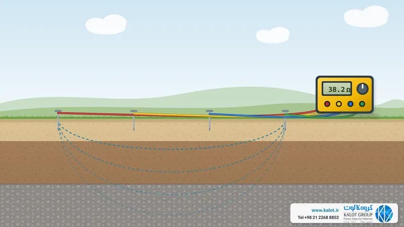
We explain how to measure earth resistance in measuring earth termination resistance, and how to install earthing inside foundations in foundation earthing.
6. Bonding and SPDs: protection inside the building
All metal pipes and structures entering the building are connected at the point of entry to an earth bar (bonding bar), such as an earth bar with disconnect link (bonding and equipotential bonding). Power and data cables cannot be connected directly to the bar, so SPDs are installed for them, such as a Class 1 three-phase power SPD in the incoming panel. See all power SPDs and data line SPDs, and read more in secondary lightning protection and types of SPD.
The IEC 62561 standard: the tests for each part
IEC 62561 is the international standard for "lightning protection system components". IEC 62305 designs the system, and IEC 62561 assesses the parts used in it. The series has eight parts, and each one defines specific laboratory tests for a group of components:
Part | Topic | Related components | Main tests |
|---|---|---|---|
Connection components | Connection clamps, earth rod couplings | Lightning current passage after salt mist and sulphurous atmosphere; Class H at 100 kA and Class N at 50 kA | |
Conductors and earth electrodes | Dimensions and material, coating thickness, bending, tensile strength, electrical resistance and copper coating adhesion | ||
Isolating spark gap (ISG) | Indirect connection to metal that must not be bonded directly | Lightning current, sparkover voltage and environmental conditions | |
Conductor holding clamps | Tape and conductor clamps for walls and roofs | Mechanical load in cold and heat, corrosion, and UV resistance for plastic clamps | |
Inspection pits and earth electrode seals | Load bearing and sealing | ||
Lightning counters | Correct counting of impulse current (Type I) or 8/20 current (Type II), counting threshold, IP rating and impact | ||
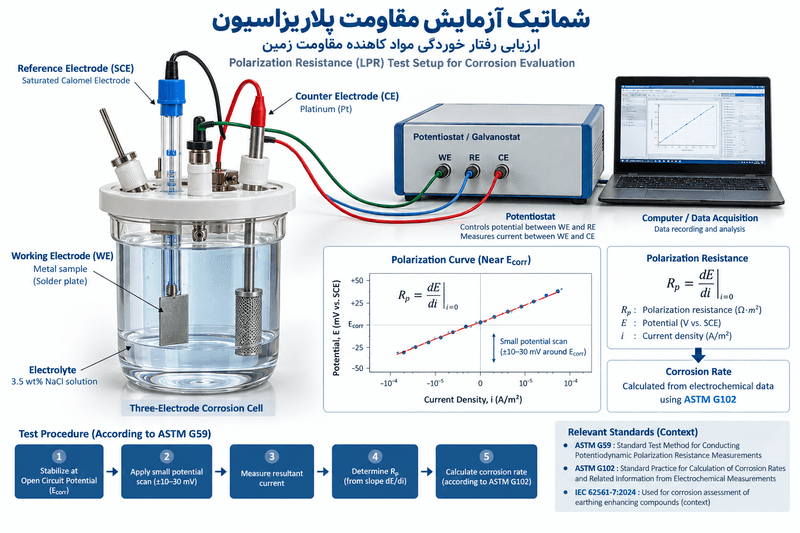
Ground improvement materials | Resistivity, leaching, sulphur content, pH and corrosion | ||
Isolated lightning protection system components | Insulating base and insulated down conductor | Impulse voltage, tension and surface contamination |
Parts 1 and 3 to 7 are now in their third edition (2023 and 2024), Part 2 received its third edition in 2025, and Part 8 moved from a technical specification to a full standard in 2026. When a seller says a part is "to IEC 62561", ask which part of the standard, which class (H or N for clamps) and in which laboratory the test was done. We list all the lightning protection standards in lightning protection standards.
Materials and dimensions: which metal, what size, next to what?
The material of a part decides two things: whether it can withstand lightning current and whether it will last for years. The table on the right of the figure below gives the minimum dimensions under IEC 62305-3. For a copper-bonded steel earth rod, IEC 62561-2 requires a copper coating at least 250 microns thick. A thinner coating soon wears away, and the steel beneath it rusts in the soil.
The second point is combining metals. When two different metals meet in the presence of moisture, one of them corrodes sooner. A few simple rules:
- Copper has no problem with brass clamps, tinned copper or stainless steel, which is why most clamps in a copper system are brass.
- Do not connect copper and galvanised steel in soil: a small galvanised part next to a large copper grid soon corrodes.
- Connect copper to a galvanised structure only in air and above ground, using a brass clamp or tinned cable lug with an anti-corrosion coating over the joint, and do not place the copper above the galvanised part.
- Protect a galvanised conductor with an anti-corrosion coating where it enters the soil, for about 30 cm above and below ground level.
Tips for installing lightning protection equipment
Even the best part will not work if it is not installed correctly. The figure below shows a sample ESE air terminal to NF C 17-102, from the tip down to the earth rod:
- Height: the tip of the ESE air terminal at least 2 m above anything on the roof, such as an antenna, air cooler or tank.
- Number of down conductors: at least two conductors for each ESE air terminal, preferably on two different facades. The IEC 62305-3 method also requires at least two down conductors.
- Clamps: three clamps per metre of down conductor in the NF C 17-102 method; in the IEC 62305-3 method, holders are usually about one metre apart. Do not drill through the conductor to fix it.
- Bends: a bend radius of at least 20 cm, with no sharp angles and no loops.
- Protective tube: the down conductor stays inside a protective tube up to at least 2 m above ground.
- Disconnector: one on each down conductor, with each conductor's earthing at less than 10 ohms in the NF C 17-102 method.
We have written up the full details of this method in 25 key points of the NF C 17-102 standard and ESE air terminals and the NF C 17-102 standard. If you entrust the work to us, our earthing, lightning protection and SPD installation team carries it out, and periodic inspection keeps the system in good condition.
Summary table: where each part goes and what it is made of
Part | Where it is installed | Common material | Product |
|---|---|---|---|
Air rod | Roof, parapet, chimney | Copper, nickel-chrome plated copper, stainless steel | |
ESE air terminal | On a mast, at the highest point of the roof | Stainless steel | |
Air rod base | Under the air rod or mast | Brass, stainless steel, galvanised steel | |
Roof and down conductors | On the roof and facade | Copper, tinned copper, stainless steel, galvanised steel | |
Holding and connection clamps | On the conductors | Brass, stainless steel | |
Disconnector and lightning counter | At the bottom of each down conductor | Brass | |
Earth rod and its clamp | In the soil | Copper-coated steel, copper, brass | |
Inspection pit | Top of the earth rod | Polyethylene, concrete | |
Earth bar and SPD | Service entry point and electrical panel | Copper |
Lightning protection equipment buying checklist
- Design first, then buy: the design drawing sets the number and length of conductors, the number of clamps and the type of earthing, not guesswork. If you have no design yet, see lightning protection system design and consultancy and lightning risk assessment.
- Keep all parts in one compatible metal family, such as a copper system with brass clamps.
- Work out the conductor's cross-section, not just the tape width.
- For each part, ask which part of IEC 62561 it was tested to.
- Calculate the number of clamps from the installation spacing, and allow a few extra for bends and corners.
- Plan one disconnector for each down conductor, and an inspection pit for the earthing system.
For a quotation, send us the drawing or dimensions of the building, the roof type, the protection method (conventional air rods or ESE air terminals) and your preferred conductor material. Our specialists will prepare the full equipment list. You can reach us through our contact page.
Conclusion
Lightning protection equipment is a chain: air termination, conductor, clamp, disconnector, earth electrode and earth bar. Every link must have the right material and dimensions, suit the link next to it and have passed the IEC 62561 tests. A part that is cheaper today but rusts or works loose a few years later becomes the most expensive part of the building on the day lightning strikes.