
Move your pointer over the image to zoom in
Complete Product Overview
Four-way conductor-to-tape clamp
Last updated:
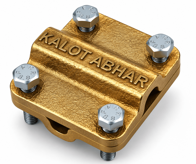
The KALOT Group four-way conductor-to-tape clamp connects copper conductor to copper or stainless steel tape in earthing, bonding and lightning protection networks. Also known as the four-way cable-to-tape clamp, it allows both cross joints and three-way branches.
The clamp body is made of high-quality brass, and its two parts are closed with four stainless steel bolts. We produce it in three models for 50, 70 and 95 mm² copper conductors and 3×30 mm tape. The specification table shows the right code for each conductor size.
Choosing the right clamp for the conductor and the joint route
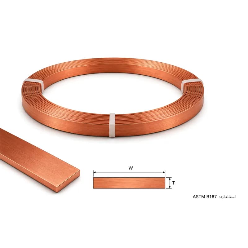
To choose this clamp, check the conductor cross-section and the tape dimensions together. Each model is designed for a specific size of copper conductor, and in all three models the tape is 30 mm wide and 3 mm thick. The tape can be copper tape or stainless steel tape; the choice of conductor material and joint location must also suit the project conditions.
The practical features of this family are:
- Two joint arrangements: suitable for conductor-and-tape crossings and for three-way branches.
- Clear selection and ordering: three models, each with its own code, matched to the copper conductor cross-section.
- Removable connection: a bolted design for inspecting the parts and for opening and reassembling the joint during service.
To match the clamp to your project's conductors, share the conductor and tape specifications and the site conditions with our experts.
Technical Product Information
Feature | Value |
|---|---|
Product type | Four-way conductor-to-tape clamp (Cable-to-Tape Connector) |
Body material | Brass |
Bolt material | Stainless steel |
Number of bolts | 4 |
Structure | Two parts: curved conductor channel in the upper part, tape groove in the lower part |
Conductor type | Bare stranded copper conductor and flat copper or stainless steel tape |
Connection type | Mechanical, bolted; crossing (through-run), straight and T arrangements |
Main application | Earthing, bonding and lightning protection system conductor networks |
Available models | CTCX 050, CTCX 070, CTCX 095 |
Related standards | IEC 62561-1 (connection components) and IEC 62305-3 (system design and installation), for reference |
How to choose a model | By conductor cross-section (50, 70 or 95 mm²); tape 30 × 3 mm |
Dimensions and product code
Conductor cross-section (mm²) | Tape dimensions (mm) | Length L (mm) | Width W (mm) | Height H (mm) | Product code |
|---|---|---|---|---|---|
50 | 30x3 | 52 | 52 | 14 | CTCX 050 |
70 | 30x3 | 54 | 54 | 16 | CTCX 070 |
95 | 30x3 | 56 | 56 | 18 | CTCX 095 |
L is the clamp's length, W its width and H its height; each dimension is marked on the drawing in the "Technical drawing and dimensions" tab. For conductor or tape of other dimensions, please talk to us before ordering.
Click to view enlarged
The drawing shows the top, front and side views of the clamp. L (length), W (width) and H (height) are marked on it, and the value of each dimension for each model is in the table in the "Technical specifications" tab. The drawing is schematic and is not a manufacturing drawing.
The PDF and SVG files of this drawing are in the "Documents and downloads" section of this page.
Click to view enlarged
Connection arrangements
- Conductor passes over the tape (crossing connection): The conductor enters the curved channel from one side and leaves from the opposite side; the tape runs at right angles through the groove of the lower part. The schematic above shows this arrangement.
- T connection: One conductor passes through the clamp, while the other ends in the clamp and branches off from the same point.
- Straight connection: The clamp is where conductor and tape join, so the route carries on from one to the other.
Assembly sequence
- Clean paint, grease, dust and heavy oxide from the surfaces of the tape, the conductor and the clamp channels.
- Place the tape in the groove of the lower part.
- Lay the conductor on the tape, at right angles to it and in line with the curved channel.
- Position the upper part so the conductor sits in its curved channel.
- Fit the four bolts by hand first, then tighten them gradually in a crosswise pattern so the two parts settle evenly on the conductors.
- After installation, check that the conductors are held firmly in the clamp and that the gap between the two parts is not uneven.
Inspection and maintenance
During periodic inspections of the earthing and lightning protection system, check this connection for loose bolts, mechanical damage, corrosion or unusual discolouration, and measure the electrical continuity of the route if needed. After any repair or opening and closing, retighten the bolts evenly.
The standards below are given to explain the requirements for this type of component and its place in the system.
System design standard: IEC 62305-3
This standard covers the design, installation, inspection and maintenance of lightning protection systems for structures, and it looks at connections from the system's point of view: keep them few, make them reliably by welding, crimping, bolting or clamping, and check them during periodic inspections. Choosing the location and number of clamps is the system designer's responsibility.
ESE lightning protection systems: NF C 17-102
If this clamp is used in the conductor network of an ESE lightning protection system (with an early streamer lead time), NF C 17-102 is the reference for the design and installation of that system, and it refers to the EN 62561 series for component requirements. This link is at system level and does not mean the clamp is approved under NF C 17-102.
Cross clamps for wire and tape
Documents & Downloads
Catalogues & datasheets
Drawings & schematics
- Dimensional drawing of the four-way conductor-to-tape clamp (PDF)Language: Persian (opens in a new tab)
- Installation schematic of the four-way conductor-to-tape clamp | round cable on copper tape (PDF)Language: Persian (opens in a new tab)
- Exploded view of the four-way conductor-to-tape clamp and its four bolt holes (PDF)Language: Persian (opens in a new tab)
- Installing the four-way conductor-to-tape clamp on a wall | Conductor and tape crossing (PDF)Language: Persian (opens in a new tab)
- Four-way conductor-to-tape clamp where the conductor crosses over the descending tape (PDF)Language: Persian (opens in a new tab)
- Three-dimensional exploded view of the four-way conductor-to-tape clamp (PDF)Language: Persian (opens in a new tab)
Frequently Asked Questions
What is a four-way conductor-to-tape clamp?
In the four-way arrangement, the conductor and the tape both run through the joint, giving four outgoing directions for the conductors. The same clamp can also be used for a three-way branch.
What is the difference between crossing, straight and T connections?
In a crossing (through-run) connection, both conductors pass through the clamp and both routes continue. In a T connection, one conductor passes through and the other branches off from the same point. In a straight connection, the clamp is the joining point of conductor and tape, so the route carries on from one to the other. This same clamp handles all three arrangements.
How do we choose the right clamp model?
Models CTCX050, CTCX070 and CTCX095 are supplied for 50, 70 and 95 mm² copper conductors respectively. The tape size for all three models is 25×3 mm.
Why is the body of this clamp made of brass?
Brass is a copper-based alloy, so using it alongside copper conductors reduces the difference between materials at the contact point. The bolts are stainless steel. Even so, for installation underground or in corrosive environments, the clamp's suitability should be checked with the KALOT technical team before work begins.
Is this clamp suitable for a lightning protection system?
This clamp is designed to connect copper conductor and tape in the conductor network of a lightning protection system. The system designer sets the location and number of connections according to IEC 62305-3 (or NF C 17-102 for an ESE system).
What should we keep in mind during installation?
Clean the surfaces of the conductors and the clamp channels, place the tape in the slot of the lower part and the conductor along the curved channel, then tighten the four bolts gradually in a crosswise pattern so the pressure is even.
How is this connection checked during periodic inspections?
Check that the bolts are tight, the body is sound and there is no corrosion or unusual discolouration, and measure the electrical continuity of the route if needed. If the connection has loosened, retighten the bolts evenly.
Can a copper conductor also be connected to a stainless steel tape?
Yes. This clamp can also connect copper conductor to 25×3 mm stainless steel tape. When ordering, please state the tape material and the installation site conditions.
What information do we need for a price enquiry?
Enter the model code, the quantity, the tape material and the installation conditions in the enquiry form. If you have not chosen a model yet, send the conductor cross-section and the tape width and thickness to our experts.
Have a Technical Question?
KALOT Group's technical experts are ready to answer your questions about lightning rods and earthing systems.