
Move your pointer over the image to zoom in
Complete Product Overview
Bare copper conductor (bare copper earth wire) for earthing and lightning protection
Last updated:
KALOT Group bare copper conductor, also known as earth wire, is an uninsulated stranded copper conductor used in earthing and lightning protection as an earth electrode, earthing conductor, down conductor and bonding conductor. We supply it in sizes from 6 to 400 mm² for a wide range of uses; the sizes most common for earthing are usually 50 to 95 mm². It is easy to lay in trenches, earth pits and around buildings, facilities and components, and is mostly used in earth grids and rings, earth pits and bonding;
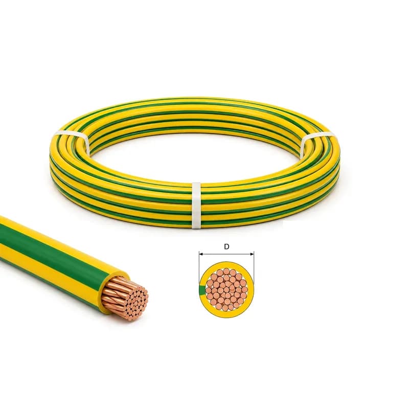
At KALOT, all bare copper conductor connections are made with copper and brass products manufactured to international standards. Widely used examples include the G-type clamp, the brass U clamp, brass conductor-to-conductor clamps, conductor-to-wall clamps, cable lugs and exothermic welding. In the soil and inside the earth pit up to the pit earth bar, bare copper conductor is used and concrete is poured around the pit; from the pit up to the main earth bar, green and yellow copper earth cable is used.
Copper conductor for earthing, from the earth pit to the roof
To choose bare copper conductor, weigh three things: the conductor's role in the design (electrode, earthing conductor, down conductor, roof network or bonding), the fault current it must carry, and where it is installed (soil, earth pit, concrete or on the building). Copper conductor works with KALOT brass clamps and exothermic welding and should not be used alongside galvanised parts.
Size 50 and above for lightning protection and electrodes
IEC 62561-2 and IEC 62305-3, for lightning protection system conductors and earth electrodes, and IEC 60364-5-54, for the earth electrode of a system with lightning protection, require stranded copper of at least 50 mm² with 1.7 mm strands; Topic 13 of the Iranian National Building Regulations considers 25 mm² sufficient for earth electrodes. The design and the fault current decide the final size.
Bare in soil and the inspection pit, green and yellow above ground
In the soil and inside the earth inspection pit, as far as the pit bar, we use bare copper conductor and pour concrete around the pit; from the pit up to the main earth bar, we use green and yellow copper earth cable. We make buried joints with exothermic welding and place clamps only inside the pit, in concrete or above ground.
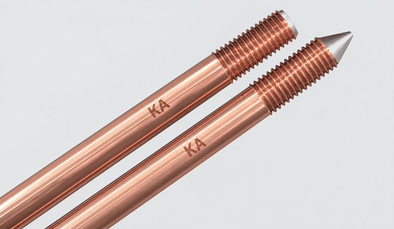
Compatible with brass clamps and copper earth rods
Bare copper conductor forms one integrated system with copper and copper-bonded earth rods, brass clamps, copper cable lugs and KALOT exothermic welding. In soil, do not connect copper conductor to galvanised parts. Make connections to galvanised structures only in air, with a tinned cable lug or brass clamp and an anti-corrosion coating, and do not install copper above galvanised parts, because copper particles washed down by rain corrode the zinc coating.
Soft or hard-drawn?
Soft conductor is for earth grids and rings, earth pits, bonding and winding routes, because it bends by hand. Choose hard-drawn conductor where it is stretched between supports and must stay straight, such as long down conductors and roof grids.
Drawings and datasheet
Bare copper conductor datasheet (PDF)The stranding and code table, earth grid schematic, roof grid and down conductor schematic, connection modes and installation steps are all here, with PDF files alongside the datasheet.
Technical Product Information
Click to view enlarged
Feature | Value |
|---|---|
Product type | Bare (uninsulated) stranded copper conductor for earthing, lightning protection and bonding |
Material | Bare copper, uninsulated |
Copper purity | 99.95 to 99.99 percent |
Conductor type | Soft (annealed) and hard-drawn |
Size (cross-section) | Soft conductor 6 to 400 and hard-drawn conductor 35 to 95 mm² |
Number of strands | Soft conductor 7, 19, 37 or 61 strands depending on size; hard-drawn conductor 7 strands (35 to 70) and 37 strands (95) |
Weight per metre | From 0.05 kg (size 6) to 3.53 kg (size 400); size 50: 0.43 kg |
Supply form | Coil or drum; coil and drum lengths to customer order |
Order code | BSCC for soft conductor and BSCD for hard-drawn conductor |
Connections | KALOT brass clamps, cable lugs and exothermic welding |
Compatibility | With copper, tinned copper and brass; no galvanised parts |
Main application | Earth grids and rings, earth pits, earthing conductors, down conductors and roof grids, bonding |
Bare copper conductor codes, sizes and weights
Order code | Type | Cross-section (mm²) | Number of strands | Weight per metre (kg) |
|---|---|---|---|---|
BSCC 006 | Soft | 6 | 7 | 0.05 |
BSCC 010 | Soft | 10 | 7 | 0.09 |
BSCC 016 | Soft | 16 | 7 | 0.15 |
BSCC 025 | Soft | 25 | 7 | 0.23 |
BSCC 035 | Soft | 35 | 19 | 0.32 |
BSCC 050 | Soft | 50 | 19 | 0.43 |
BSCC 070 | Soft | 70 | 19 | 0.62 |
BSCC 095 | Soft | 95 | 19 | 0.86 |
BSCC 120 | Soft | 120 | 37 | 1.09 |
BSCC 150 | Soft | 150 | 37 | 1.33 |
BSCC 185 | Soft | 185 | 37 | 1.67 |
BSCC 240 | Soft | 240 | 61 | 2.20 |
BSCC 300 | Soft | 300 | 61 | 2.76 |
BSCC 400 | Soft | 400 | 61 | 3.53 |
BSCD 035 | Hard-drawn | 35 | 7 | 0.32 |
BSCD 050 | Hard-drawn | 50 | 7 | 0.43 |
BSCD 070 | Hard-drawn | 70 | 7 | 0.62 |
BSCD 095 | Hard-drawn | 95 | 37 | 0.86 |
"Size" is the conductor's nominal cross-section in mm²; standards determine the cross-section of a stranded copper conductor from its electrical resistance (IEC 60228). We supply bare copper conductor in coils or on drums, cut to the length you order. Our products are continually improved and some dimensions may be updated, so please confirm final dimensions with our specialists before you buy.
Stranding, coils and code table
Download stranding, coils and code table (PDF)
Structure and supply form of bare copper conductor
Bare copper conductor is made of copper strands wound in concentric layers around a central strand: 7, 19, 37 or 61 strands depending on the size. Soft (annealed) conductor is heat treated after drawing and bends easily; hard-drawn conductor does not undergo this heat treatment, has higher tensile strength and stays straighter on stretched runs. We supply it in coils for short lengths and on drums for long lengths, cut to the length you order.
Click to view enlarged
Applications of bare copper conductor in earthing and lightning protection
- Earth grids and earth rings: horizontal electrodes around a building, 1 m from the outer walls, and earth grids in substations, power plants and factories, at a depth of 70 to 80 cm, with buried joints made by exothermic welding.
- Connecting earth rods: linking copper-bonded earth rods and copper earth rods to each other and to the inspection pit earth bar, with a brass clamp on the top of the earth rod, inside the pit.
- Earth pits: according to Topic 13, bare copper conductor is better than a copper plate in an earth pit: it costs less, and the electrode and earthing conductor are one piece with no joint. We lay the end of the conductor in the pit as a five-turn spiral, 50 cm in diameter, and bring the bare conductor up in one piece to the inspection pit earth bar; from the inspection pit up to the main earth bar, green and yellow copper earth cable is used. For earth pits, we recommend size 50 conductor.
- Earthing conductor: from the electrode to the main earth bar; the part bare in the soil must match the electrode size, and from the inspection pit upwards green and yellow copper earth cable is used.
- Down conductors and roof grids: down conductors at the corners of the building and at intervals of 10 to 20 m around it (depending on the protection class), and the air-termination conductor grid on the roof, with two-piece brass clamps, one-hole copper clips (OHCC) and four-way conductor-to-conductor clamps. To get to know the components, see The lightning protection system and its components.
- Bonding: connecting bonding bars, steel frames and tanks, towers and cable trays to the earthing system, with TECD clamps, TECS and PTEC and cable lugs. Make connections to a galvanised tower, structure or cable tray only in air and above ground level, use a tinned cable lug or brass clamp, cover the joint with an anti-corrosion coating, and do not run copper conductor above galvanised parts; see Bonding and equipotential bonding.
- Foundation earthing: bare copper conductor can also be used in concrete and on foundation reinforcement, and connected directly to the reinforcing bars; see Earthing systems based on foundation earthing.
Earth grid with bare copper conductor and earth rods
Download earth grid schematic (PDF)
Roof grid and down conductor with bare copper conductor
Download roof grid and down conductor schematic (PDF)
Connection modes of bare copper conductor with KALOT brass clamps and exothermic welding
Download connection modes (PDF)
Installation steps for bare copper conductor
- Take the grid route and the positions of the earth rods, inspection pits and main earth bar from the earthing drawing, and choose the conductor size based on its role and the fault current.
- Dig the trench to a depth of 70 to 80 cm; in cold regions, lay the conductor below frost depth. IEC 62305-3 requires the earth ring at least 0.5 m below ground, Topic 13 places horizontal electrodes at a depth of 0.5 to 0.8 m, and the Earthing System Installation Guideline at a depth of at least 0.7 m.
- Unwind the conductor from the coil or drum without kinks or knots, and take care that the strands do not separate. In trenches we recommend soft conductor, because it bends by hand and in soil there is no need for the tensile strength of hard-drawn conductor.
- Drive the earth rods at each inspection pit position: copper-bonded earth rods or copper earth rods.
- Inside the earth inspection pit, fix the bare conductor to the top of the earth rod with a G-type clamp or brass U clamp, and use a cable lug to connect it to the pit bar; pour concrete around the inspection pit. Tighten the nuts according to the installation instructions on that clamp's product page.
- Make crossings and branches that will be buried in the soil with exothermic welding; do not bury clamps in soil, and use them only inside the inspection pit, in concrete or above ground.
- Backfill the trench with soft, moist soil free of stones, construction waste and charcoal, and compact it; in high-resistivity soil, surround the conductor with GIM ground improvement material.
- From the inspection pit up to the main earth bar, use green and yellow copper earth cable.
- Down conductors and roof grids: bring the down conductor down directly by the shortest route, and do not place it inside gutters or rainwater pipes. According to IEC 62305-3, fix bare copper conductor with a brass clamp every 1 m on vertical runs up to a height of 20 m and on horizontal roof surfaces, and every 0.5 m on horizontal runs on walls or parapets and vertical runs above 20 m. At the foot of each down conductor, the bare conductor reaches the earth rod inside the earth inspection pit.
- Join roof grid crossings with a four-way conductor-to-conductor clamp or three-way clamp, and fit a test joint on each down conductor, above ground level, that opens only with a tool.
- After installation, measure the continuity of the route and test the earth resistance at the open test joint; record the result with the date in the earthing system file.
Download the installation steps (PDF)
Installation tools
Spanner for clamp nuts, hydraulic cable lug press, exothermic welding mould and weld powder, cable cutters, tape measure, continuity tester (milliohmmeter), earth resistance tester and a camera to record the route before backfilling the trench or pouring concrete.
Continuity checks, measurement and inspection
Joints in trenches and concrete cannot be seen once covered, so before that, check the conductor route and every joint and record them with drawings and photos. At each inspection, check the tightness of the clamps inside the inspection pit and on the building, the condition of the conductor where it enters the soil and concrete, and the earth resistance at the test joint. The green surface that copper conductor develops in air is copper's natural protective layer; but if the resistance of a joint has risen, clean it and retighten it. IEC 62305-3:2010 recommends maximum inspection intervals for lightning protection systems: at protection levels I and II, a visual inspection every year and a complete inspection every 2 years; at protection levels III and IV, a visual inspection every 2 years and a complete inspection every 4 years; in critical situations (structures with sensitive internal systems, office and commercial buildings and densely occupied places), a complete inspection every year; and for structures with a risk of explosive materials, a visual inspection every 6 months and an electrical test every year. For the measurement method, see How is earth terminal resistance measured?
Choosing bare copper conductor and requesting a quote
To request a quote for bare copper conductor, send our specialists the size (cross-section), type (soft or hard-drawn), length and supply form (coil or drum), application (earth grid, earth pit, down conductor, roof grid or bonding) and the clamps and accessories you need (earth rod clamps, conductor-to-conductor clamps, wall clamps, cable lugs, exothermic welding, earth inspection pits and green and yellow copper earth cable). If you also send the project's earthing drawing or lightning protection design, our specialists at KALOT Group will give you the list of conductors and accessories along with the current price.
Click to view enlarged
Copper is stable against corrosion in most soils and in air, and it conducts better than the other metals in an earthing system, so a copper conductor with a smaller cross-section carries the same current. Bare copper conductor is flexible, bends in trenches, earth pits and around components, and seats in clamp saddles. A few points to bear in mind: IEC 62305-3 notes that copper corrosion increases with sulphur compounds, organic materials and acidic or ammoniacal soil, and that stranded conductor is more vulnerable to corrosion than solid conductor, especially where it enters soil and concrete. That is why we take care with these entry points, check them at every inspection and place mechanical joints only inside the earth inspection pit, in concrete or above ground. In soil, do not connect copper to galvanised steel; make connections to galvanised structures only in air, with a tinned cable lug and an anti-corrosion coating, and do not install copper above galvanised parts.
Advantages of KALOT bare copper conductor
- Higher conductivity: copper conducts better than the other metals in an earthing system, so the same current is carried with a smaller cross-section.
- Stable in soil and air: copper is stable against corrosion in most soils, in air and in concrete.
- Flexible: soft conductor bends by hand and is easily installed in trenches, earth pits and around components.
- From 6 to 400: a complete family, from bonding internal services to substation earth grids, in soft and hard-drawn.
- Connected with KALOT products: brass clamps, cable lugs, exothermic welding, earth inspection pits and pit bars from a single supplier; we connect size 400 conductor with exothermic welding.
- Supplied in coils and on drums: cut to the length you order, so long routes run without joints.
Choosing the copper earth conductor size by its role in the design
Conductor role | Installation location | Minimum size in the standards (mm²) | Our recommendation |
|---|---|---|---|
Earth electrode and earth ring in a lightning protection system | Soil, 70 to 80 cm deep | 50, with 1.7 mm strands | BSCC 050 and above |
Earth electrode, only for protection against electric shock | Soil | 25 | BSCC 025 or BSCC 050 |
Earth pit with a five-turn spiral | Earth pit | 35 | BSCC 050 |
Earthing conductor, with a lightning protection system | From the electrode to the main earth bar | 16; bare part in soil 50 | BSCC 050 in soil and the inspection pit; green and yellow copper earth cable from the pit upwards |
Down conductors and roof grids | On the building | 50 | BSCC 050 or BSCD 050 |
Bonding bars to the earthing system | Inside the building | 16 | BSCC 016 and above |
Bonding metal services inside the building | Inside the building | 6 | BSCC 006 and above |
Substation and power plant earth grids | Soil | Based on the fault current | BSCC 070 to BSCC 400 |
Sizes are taken from IEC 62561-2:2018, IEC 62305-3:2010, IEC 60364-5-54:2011, Topic 13 of the Iranian National Building Regulations and the Guideline for Installing Earthing Systems in Buildings; the design and the fault current decide the final size. For conductor and electrode materials, see Earth electrode materials.
See these products too
Product | When |
|---|---|
Insulated conductor for the run from the earth inspection pit up to the main earth bar. | |
Vertical electrode; bare copper conductor links the earth rods to each other. | |
Solid copper vertical electrode for corrosive soils. | |
Conductors 16 to 120 on the top of earth rods of 14 to 20 mm, inside the inspection pit. | |
Conductors 6 to 300 on earth rods or reinforcing bars. | |
Two parallel conductors of 25 to 185 mm². | |
Crossings of 50, 70 and 95 conductors in the roof grid. | |
Test joint for the down conductor, above ground level. | |
Fixes 50 to 95 down conductors on walls. | |
For an inspectable connection on the top of the earth rod; concrete is poured around it. | |
Precast inspection pit for an inspectable connection on the top of the earth rod. | |
Bolted branch joint for conductors 10 to 240. | |
Crimped, permanent branch joint for conductors 10 to 240. | |
Connection point for bare conductors with cable lugs inside the inspection pit. | |
Permanent joint of conductor to conductor, to earth rod, to reinforcing bar and to steel structure. |
Compare all earthing and bonding clamps in the "Which clamp should we choose?" table.
IEC 62561-2:2018 (lightning protection system components: conductors and earth electrodes) gives, for stranded copper air-termination conductors and down conductors, a minimum cross-section of 50 mm² with recommended strands of 1.14 to 1.7 mm, and for earth electrode conductors, 50 mm² with 1.7 mm strands. The same standard determines the cross-section of stranded copper conductor from its electrical resistance according to IEC 60228, and requires for copper a maximum resistivity of 0.018 microhm-metres and a tensile strength of 200 to 450 N/mm².
IEC 62305-3:2010 (protection of structures against lightning) sets the minimum cross-section of stranded copper conductor at 50 mm² for air-termination conductors, down conductors and earth electrodes, 16 mm² for bonding conductors between bars and the earthing system, and 6 mm² for bonding metal services inside the building. It requires the earth ring at least 0.5 m below ground and 1 m from the outer walls, sets the minimum strand diameter at 1.7 mm, and notes that stranded conductor is more vulnerable to corrosion than solid conductor, especially where it enters soil and concrete. The same standard says a copper part must not be installed above an unprotected galvanised part, because fine copper particles corrode the zinc coating even without contact. It does not accept clamped joints in soil unless they have effective corrosion protection, and it reports good experience with crimped joints in soil. We do not bury clamps in soil, and we make buried joints with exothermic welding.
IEC 60364-5-54:2011 (earthing arrangements and protective conductors) requires 50 mm² with 1.7 mm strands for a stranded copper earth electrode, and accepts 25 mm² if the electrode is only for protection against electric shock. It recommends a copper earthing conductor of at least 6 mm² and, when a lightning protection system is connected to the electrode, at least 16 mm²; the part of the earthing conductor that is bare in soil must match the electrode size. Joints are made with exothermic welding, pressure connectors, clamps or suitable mechanical connectors, and a joint that relies only on solder is not accepted. The cross-section needed for the fault current is calculated with the formula S = I√t / k.
Topic 13 of the Iranian National Building Regulations (1395 edition) specifies 25 mm² for an earth electrode of bare multi-strand copper conductor, with strands of at least 1.7 mm, and places horizontal electrodes at a depth of 0.5 to 0.8 m. In earth pits, it considers bare copper conductor better than a copper plate and recommends coiling its end into a five-turn spiral, each turn 50 cm in diameter. It sets the minimum cross-section of the main earth bar with a copper conductor at 50 mm², and in its metal compatibility table considers bonding a galvanised steel electrode to copper unsuitable.
The Guideline for Installing Earthing Systems in Buildings requires 25 mm² with 1.7 mm strands for a stranded copper conductor electrode and, when the copper conductor itself is the earth pit electrode, at least 35 mm² with at least five turns. It installs horizontal electrodes at a depth of at least 0.7 m and below frost depth.
BS 7430:2011 (code of practice for earthing) points out that strands must not separate when stranded conductor is pulled, that fixing clamp spacing must not exceed 1 m, and that copper conductor must not be drilled for installation. The same code accepts crimped joints for stranded conductor, and exothermic welding, zinc-free brazing or bolting for copper-to-copper joints.
Stranded bare copper wire: section and use
Documents & Downloads
Catalogues & datasheets
Drawings & schematics
- Bare copper conductor stranding, coil and code tableLanguage: Persian (opens in a new tab)
- Earthing network schematic with bare copper conductorLanguage: Persian (opens in a new tab)
- Roof network and down conductor schematic with bare copper conductorLanguage: Persian (opens in a new tab)
- Bare copper conductor connection modesLanguage: Persian (opens in a new tab)
- Bare copper conductor installation stepsLanguage: Persian (opens in a new tab)
Frequently Asked Questions
What is a bare copper conductor, and how does it differ from green and yellow earth cable?
A bare copper conductor is an uninsulated stranded copper conductor, used in soil, inside the earth inspection pit, in concrete and on buildings as an electrode, earthing conductor, down conductor and bonding conductor. The green and yellow copper earth cable is the same copper conductor with a PVC sheath, and we recommend it for the run from the inspection pit up to the main earth bar and for bonding equipment above ground. In the soil and inside the pit, as far as the pit bar, use only bare conductor.
Which size of copper earth conductor should I use, 50 or 70?
The size depends on the conductor's role and the fault current. IEC 62561-2, IEC 62305-3 and IEC 60364-5-54 require at least 50 mm² of stranded copper for earth electrodes and lightning protection system conductors. IEC 60364-5-54, for an electrode used only for protection against electric shock, and Topic 13 of the Iranian National Building Regulations, for earth electrodes, accept 25 mm². In large grids and substations, the fault current calculation decides on size 70 and above. The "Choosing the copper earth conductor size" table on this page shows the size for each role.
How many strands does a size 50 copper conductor have, and how much does a metre weigh?
Our size 50 soft conductor (BSCC 050) has 19 strands and our size 50 hard-drawn conductor (BSCD 050) has 7 strands; both weigh 0.43 kg per metre. The weight and strand count of every size, from 6 to 400, are in the code table on this page.
Soft or hard copper conductor: which should I buy for earthing?
For earth grids and rings, earth pits and bonding, we recommend soft (annealed) conductor: it bends by hand, lays easily in trenches and around components, and conducts slightly better. Hard-drawn conductor has higher tensile strength and suits runs stretched between supports that must stay straight, such as long down conductors and roof grids. IEC 62561-2 has one specification row for copper (tensile strength 200 to 450 N/mm²) and does not specify whether the conductor is soft or hard.
How do I connect a bare copper conductor to an earth rod?
Inside the earth inspection pit, fix the conductor to the top of the earth rod with a G-type clamp (conductors 16 to 120 on earth rods of 14 to 20 mm), a brass U clamp (conductors 6 to 300) or, for two conductors, a three-piece U clamp. For a permanent joint, use exothermic welding of conductor to earth rod. Tighten the nuts according to the installation instructions on that clamp's product page, and pour concrete around the pit.
How deep should a bare copper conductor be buried, and what should surround it?
IEC 62305-3 requires the earth ring at least 0.5 m below ground, Topic 13 places horizontal electrodes at a depth of 0.5 to 0.8 m, and the Earthing System Installation Guideline at a depth of at least 0.7 m. We recommend 70 to 80 cm, and in cold regions below frost depth. Backfill the trench with soft, moist soil free of stones, construction waste and charcoal; in high-resistivity soil, surround the conductor with GIM ground improvement material.
Must the conductor inside the earth pit and the inspection pit be bare?
Yes, that is how we install it: in the soil and inside the earth inspection pit, as far as the pit bar, we use bare copper conductor; Topic 13 treats the part of the earthing conductor lying in soil or concrete as part of the electrode. From the pit up to the main earth bar, use green and yellow copper earth cable and pour concrete around the pit.
Can a bare copper conductor be connected to galvanised tape, earth rods or structures?
Not in soil: galvanised steel corrodes where it joins copper. So in a copper earthing network, use copper or copper-bonded earth rods, brass clamps, copper cable lugs and exothermic welding, and connect no galvanised tape, earth rod or clamp to the copper conductor in the soil. Connecting to a galvanised tower, structure or cable tray in air is possible: use TECD clamps, TECS and PTEC or a tinned cable lug, above ground level, and cover the joint with an anti-corrosion coating; Topic 13 considers bonding a copper conductor to a larger galvanised structure suitable. IEC 62305-3 points out that a copper part must not be installed above an unprotected galvanised part, because copper particles washed down by rain corrode the zinc coating.
Which is better, bare copper conductor or copper tape?
Both are used, and the choice depends mostly on the design and the installation location. Bare copper conductor bends easily, seats in clamp saddles and exothermic welding moulds, and goes into an earth pit as a spiral; copper tape sits flat on walls and, for the same cross-section, has more contact surface with the soil. IEC 62305-3 regards stranded conductors as more vulnerable to corrosion than solid ones, so in corrosive soils, take extra care with joints and the transition from soil to air.
What spacing should clamps have for a bare copper conductor on a wall?
IEC 62305-3:2010 recommends, for bare copper conductor, support spacing of 1000 mm on vertical runs up to a height of 20 m and on horizontal surfaces, and 500 mm on horizontal runs on walls and vertical runs above 20 m. For fixing, use a two-piece brass clamp or a one-hole copper clip (OHCC); do not drill the copper conductor to install it.
What fault current can a size 50 bare copper conductor withstand?
IEC 60364-5-54 calculates the required cross-section with the formula S = I√t / k. For bare copper with a starting temperature of 30 and a final temperature of 200 degrees Celsius (normal conditions), k is 159, so a 50 mm² conductor withstands 50 × 159, that is 7950 A, for one second. If the fault path includes a bolted joint, BS 7430 limits the final temperature to 250 degrees; do not assume a final temperature higher than this. These figures are a standard calculation, and the designer chooses the final size based on the project's current and disconnection time.
What is the copper purity of KALOT bare copper conductor?
The copper in our bare conductor has a purity of 99.95 to 99.99 percent. IEC 62561-2:2018 sets a maximum resistivity of 0.018 microhm-metres for the copper in lightning protection system conductors; the cross-section of a stranded conductor is also determined by its electrical resistance.
In what lengths is bare copper conductor supplied: coil or drum?
We supply bare copper conductor in coils for short lengths and on drums for long lengths, cut to the length you order. Run long routes without joints wherever possible; IEC 62305-3 asks for as few joints as possible.
How is the price of copper earth conductor set, and what should I send for a quote?
The price depends on the size, length, type (soft or hard-drawn) and the day's copper price. Send our specialists the size, length, type, application (earth grid, earth pit, down conductor, roof grid or bonding) and the clamps you need, and they will give you the current price along with a list of accessories.
Have a Technical Question?
KALOT Group's technical experts are ready to answer your questions about lightning rods and earthing systems.