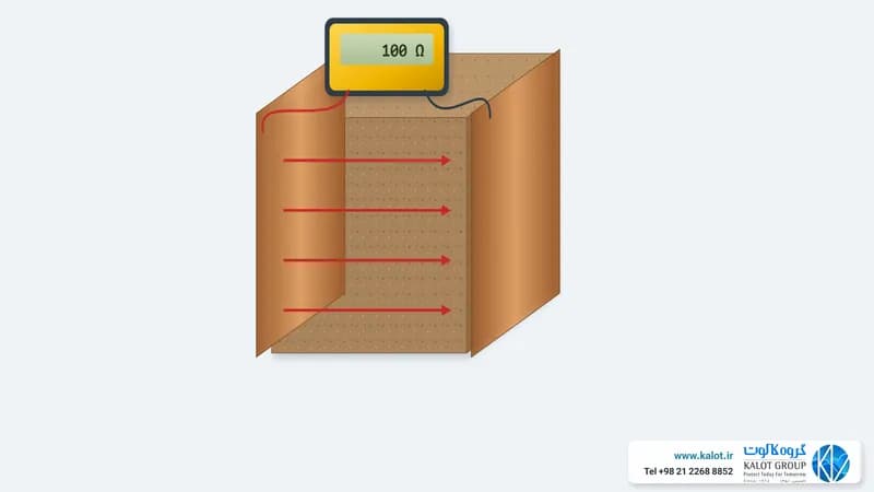
Soil electrical resistivity (Soil Resistivity) is one of the key parameters in designing and building an earthing system. It expresses how strongly a given volume of soil resists the flow of electric current.
This property shows how well the soil can carry current from the earth electrode into the surrounding soil. The lower the soil resistivity, the better and more safely the current is transferred, and the more effective the earthing system design will be.
Soil resistivity is normally measured in ohm-metres (Ω·m). It depends directly on the physical and chemical make-up of the soil, its moisture content, temperature, compaction and salinity, and the type of minerals present.
Moist clay soils have lower resistivity, while sandy, rocky or dry soils show higher values.
Why resistivity matters in earthing design
The main goal in designing an earthing system is a low, stable resistance that protects equipment and keeps people safe. That is why knowing the soil resistivity where the electrode will be installed is the first step in calculating and designing a suitable earthing system.
Where resistivity is high, methods such as adding ground improvement materials, increasing the electrode depth, or designing radial and extended networks should be used to lower the overall resistance of the system.
How soil resistivity is measured (the Wenner test)
One of the standard and most widely used ways to measure soil resistivity is the Wenner four-electrode method (Wenner Method).
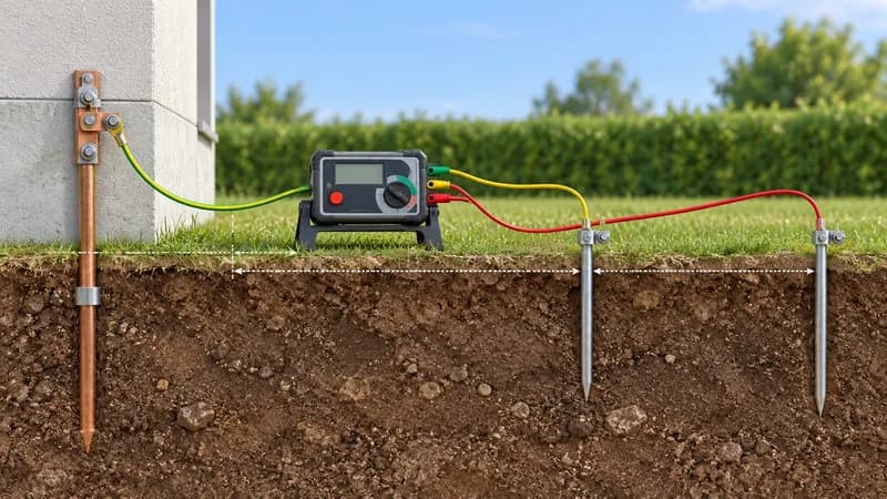
Four metal spike electrodes are driven into the soil in a straight line at equal spacing. Current is passed through the two outer electrodes, the potential difference between the two inner electrodes is measured, and the soil resistivity is calculated from the result.
In the Wenner method, four electrodes are set in the soil in a straight line to measure resistivity.
The Wenner calculation formula is:
ρ = 2πaR
where:
- ρ = soil resistivity (ohm-metres)
- a = distance between electrodes (metres)
- R = resistance measured by the instrument (ohms)
By repeating the test at different spacings, you can see how resistivity changes with depth and analyse the electrical conductivity of the different soil layers.
We cover the step-by-step Wenner and Schlumberger methods, electrode spacing, a comparison of the two methods and common field errors in our guide to measuring earth resistance and soil resistivity.
Factors that affect soil resistivity
- Soil moisture: higher moisture lowers resistivity considerably.
- Temperature: below zero degrees, freezing of the soil increases resistivity.
- Soil composition: clay soils and salt-rich soils have higher conductivity.
- Density and compaction: the more compact the soil, the greater the contact between particles and the lower the resistance.
- Chemical or mineral substances: materials containing salts or metallic compounds increase the electrical conductivity of the soil.
Approximate resistivity values for different soil types
Soil type | Probable value: normal and high rainfall (over 500 mm a year) | Range of values: normal and high rainfall | Range of values: low rainfall and desert (under 250 mm a year) | Range of values: saline groundwater |
|---|---|---|---|---|
Alluvium and light clays | 5 | Depends on the local groundwater level | Depends on the local groundwater level | 1 – 5 |
Clays (excluding alluvium) | 10 | 5 – 20 | 10 – 100 | 1 – 5 |
Marls (such as Keuper marl) | 20 | 10 – 30 | 50 – 300 | — |
Porous limestone (such as chalk or white clay) | 50 | 30 – 100 | — | — |
Porous sandstone (such as Keuper sandstone and clay shales) | 100 | 30 – 300 | — | — |
Quartzite, compact and crystalline limestone (Carboniferous sediments, marble and similar) | 300 | 100 – 1000 | — | — |
Clay slates and slaty shales | 1000 | 300 – 3000 | 1000 and above | 30 – 100 |
Granite | 1000 | — | — | — |
Laminated shales, schist, gneiss and igneous rocks | 2000 | 1000 and above | — | — |
Source: Table 2 of BS 7430:2026 (typical soil resistivity values in ohm-metres). The standard itself says these figures are very general and only indicate how difficult designing an earthing system at a given site may be; they do not replace on-site measurement. The saline groundwater column relates mostly to marshy land beside river estuaries.
Choosing the right location and using the best materials for reducing soil resistance therefore plays an important part in the performance of the earthing system and in electrical protection.