
Move your pointer over the image to zoom in
Complete Product Overview
Two-way conductor-to-tape clamp
Order Code: ITCT 5253 · 5303 · 5503 · 7253 · 7303 · 7503
Last updated:
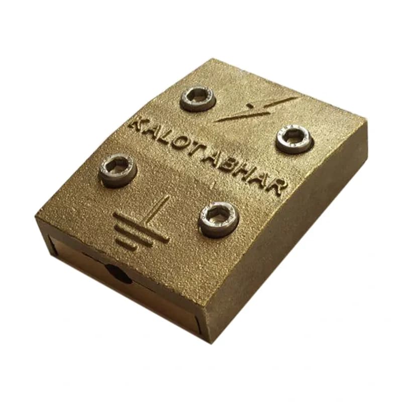
The KALOT two-way conductor-to-tape clamp (Interface Test Clamp) joins copper tape end to end with stranded round copper conductor, for example when a lightning protection down conductor is run in tape but the connection to the earth electrode uses round conductor.
This clamp is usually the down conductor's test point as well: undoing the nut on the bolt separates the round conductor from the tape, so the earthing system resistance can be measured on its own, and the connection is closed again after the test.
We manufacture this clamp from two brass plates with one stainless steel bolt (with nut and washer), in six models: for 50 or 70 mm² conductor and 25×3, 30×3 or 50×3 mm tape, from ITCT 5253 to ITCT 7503.
From facade tape to round earthing conductor
In many projects, the down conductor on the facade is run in copper tape, while the connection to the earth electrode uses stranded round conductor. The KALOT two-way conductor-to-tape clamp joins the two at one accessible point, the same point that NF C 17-102 requires for testing each down conductor, usually about 2 m above ground level.
From tape to round conductor
The tape enters from the wide edge of the clamp and the round conductor from the narrow edge, and both are pressed together between two brass plates.
Test point for the earthing system
Undoing the nut separates the round conductor from the tape, so the earthing system resistance is measured without the effect of parallel paths.
Six models for six combinations
50 or 70 mm² conductor with 25×3, 30×3 or 50×3 tape; each model is made precisely for its own combination.
Brass with a stainless steel bolt
The two brass plates are compatible with copper conductor and tape, and the stainless steel bolt keeps its durability outdoors.
One bolt, quick installation
One bolt with nut and washer holds both conductors at once, so installation, inspection and reclosing are simple.
Technical Product Information
Feature | Value |
|---|---|
Product type | Two-way conductor-to-tape clamp (Interface Test Clamp) |
Application | End-to-end connection of copper tape to stranded round copper conductor; down conductor test point |
Round conductor | 50 or 70 mm², stranded copper |
Tape | 25×3, 30×3 or 50×3 mm, copper |
Body material | Brass (two plates) |
Bolt | 1, stainless steel, with nut and washer |
Structure | Two trapezoidal plates; tape enters from the wide edge and round conductor from the narrow edge |
Dimensions | L = 54 mm, W = 35 / 37 / 40 mm, H = 6 mm |
Order code | ITCT 5253 to ITCT 7503 (six models) |
Our products are continually improved and some dimensions may be updated; please confirm the final dimensions with our specialists before you buy.
Order code | Round conductor (mm²) | Tape (mm) | L (mm) | W (mm) | H (mm) |
|---|---|---|---|---|---|
ITCT 5253 | 50 | 25×3 | 54 | 35 | 6 |
ITCT 5303 | 50 | 30×3 | 54 | 37 | 6 |
ITCT 5503 | 50 | 50×3 | 54 | 40 | 6 |
ITCT 7253 | 70 | 25×3 | 54 | 35 | 6 |
ITCT 7303 | 70 | 30×3 | 54 | 37 | 6 |
ITCT 7503 | 70 | 50×3 | 54 | 40 | 6 |
Choose the model by the cross-section of the round conductor and the tape dimensions: the first two digits of the code show the conductor cross-section (50 or 70), and the digits after them show the tape dimensions. For other combinations, our specialists at KALOT Group will be glad to guide you.
Click to view enlarged
The KALOT dimensional drawing shows the front and side views of the clamp: the trapezoidal brass plate with a hexagon bolt in the centre, tape entry from the wide edge and round conductor entry from the narrow edge, along with a table of the six models. Dimensions: L = 54 mm, W = 35 / 37 / 40 mm, H = 6 mm. The PDF and SVG files are in the "Documents and downloads" section of this page.
Click to view enlarged
The clamp's place in the system
The clamp sits on each down conductor, between the facade tape and the round conductor of the earthing system. Under NF C 17-102, the test joint of each down conductor is usually installed about 2 m above ground level, where it is accessible for inspection and safe from tampering. Below the clamp, the round conductor continues inside a protective pipe to below ground level.
Installation sequence
- Choose the clamp model by the cross-section of the round conductor and the tape dimensions.
- Clean dirt, oxide and oil from the contact surfaces of the tape and conductor.
- Undo the nut so the two clamp plates move apart.
- Place the tape between the two plates from the wide edge and the round conductor from the narrow edge.
- Tighten the nut gradually with a spanner until both conductors are pressed firmly between the two plates.
- Hold the tape above the clamp on the facade with a wall clamp, and run the conductor below the clamp inside a protective pipe to the earthing system.
- Check the continuity of the route from the down conductor to the earthing system.
Testing the earthing system
- Carry out the test in calm weather; do not open the connection in stormy conditions or when lightning is possible.
- Undo the nut on the bolt with a spanner and separate the round conductor from the tape.
- Measure and record the earthing system resistance from the round conductor side with an earth tester; in systems designed to NF C 17-102, this value must be 10 ohms or less.
- Put the round conductor back in place, tighten the nut and check the continuity of the route.
Choosing the right clamp
- Tape to round conductor, end to end and testable: this clamp, ITCT 5253 to ITCT 7503.
- 25×3 tape to 50 mm² conductor with a cast four-bolt body on the wall: SKADL 100 brass disconnector.
- Test joint between two round conductors: Two-way conductor-to-conductor clamp.
- Cross connection of round conductor and tape: Four-way conductor-to-tape clamp.
- Holding the tape on the wall: Two-piece brass clamp for fixing tape to walls or Two-piece stainless steel clamp for fixing tape to walls.
Technical notes
- In normal operation the clamp must stay closed; open it only for testing and close it again straight away.
- The brass plates are compatible with copper tape and conductor. Avoid direct connection of aluminium or galvanised steel conductors, and leave material compatibility to the system designer.
- For connections buried in soil or concrete, the designer should decide the connection method; many designs make these connections by exothermic welding.
The following standards set out the place and requirements of test joints and connection components in a lightning protection system:
NF C 17-102 (ESE air terminals)
Each down conductor needs a test joint so the conductor can be separated from the earthing system for measurement; this joint is usually installed about 2 m above ground level. Read the key points of the NFC 17-102 standard in this article.
IEC 62305-3 (system design and installation)
Where the earthing system connects to the down conductor, a test joint is fitted on each down conductor. It is opened with a tool for measurement and stays closed in normal operation.
IEC 62561-1 (connection components)
This standard sets the requirements and tests for the connection components of a lightning protection system, including test joints and conductor-to-conductor clamps.
Test joint and down conductor test clamps
Documents & Downloads
Catalogues & datasheets
Drawings & schematics
Installation & application guides
Frequently Asked Questions
What is the two-way conductor-to-tape clamp used for?
This clamp joins copper tape end to end with stranded round copper conductor, for example between the down conductor tape on the facade and the round conductor of the earthing system. This same point is usually the down conductor's test joint as well.
Which model should I choose?
By the cross-section of the round conductor (50 or 70 mm²) and the tape dimensions (25×3, 30×3 or 50×3). For example, ITCT 5253 for 50 conductor with 25×3 tape, and ITCT 7503 for 70 conductor with 50×3 tape.
Can this clamp be used as a test clamp?
Yes. Undoing the nut on the bolt separates the round conductor from the tape, so the earthing system resistance can be measured on its own. After the test, the connection is closed again.
At what height should we install this clamp?
When it serves as the test joint, under NF C 17-102 it is usually installed about 2 m above ground level, where it is accessible for inspection but not exposed to tampering.
What are the clamp and bolt made of?
The clamp body consists of two brass plates, closed by one stainless steel bolt with nut and washer.
How does this clamp differ from the SKADL 100 brass disconnector?
Both connect a down conductor tape to the round earthing conductor, and both can be tested. The SKADL 100 disconnector has a cast four-bolt body, mounts on the wall and is for 25×3 tape and 50 mm² conductor. This clamp has one bolt and six models for different combinations of tape and conductor.
How does this clamp differ from the four-way conductor-to-tape clamp?
This clamp joins tape and round conductor end to end, in line with each other. The four-way clamp connects round conductor and tape in a cross or in parallel.
Is this clamp suitable for buried connections?
This clamp is made for accessible connections on the structure. For connections buried in soil or concrete, the system designer decides the connection method, and many designs use exothermic welding.
Have a Technical Question?
KALOT Group's technical experts are ready to answer your questions about lightning rods and earthing systems.