Short answer: a foundation earth (Foundation Earth Electrode) is a steel conductor placed as a closed ring inside the foundation concrete while the building goes up. It connects to the reinforcing bars at least every 2 m and reaches the main earth bar and the lightning protection system through terminal branches. Because foundation concrete holds moisture and has a large surface in contact with the soil, a foundation earth gives a low, lasting earth resistance with no extra excavation. If the foundation is separated from the soil by a waterproofing layer or thermal insulation, an earth ring is installed in the soil outside the foundation instead.
In this guide, we at KALOT Group draw on Iranian National Standard 23064, the German standard DIN 18014:2023 and the British standard BS 7430:2026 to explain what a foundation earth is made of, how the foundation earth bonding drawing is prepared, how the connection to reinforcing bars should be made, which conductor materials and sizes are suitable, and what must be tested and recorded before the pour. You can also download the full text of the national standard from this page.
What are foundation earthing and foundation bonding, and why are they the best start for a building?
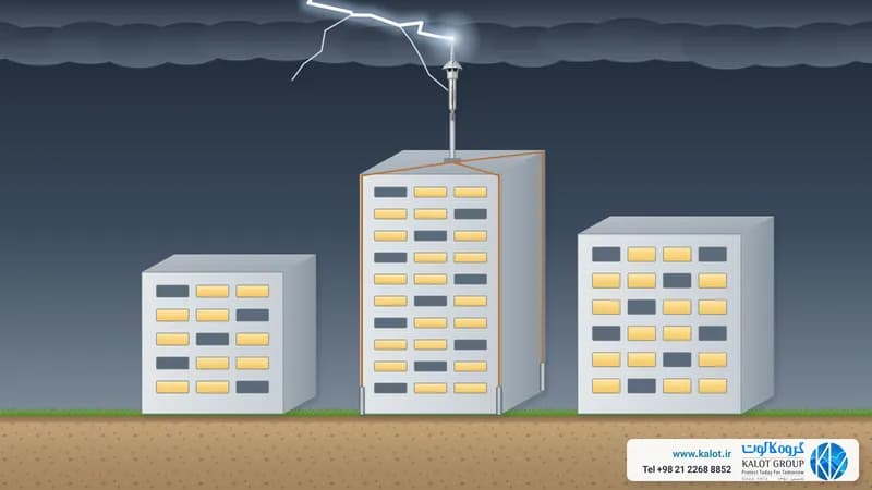
Every building needs a building earthing system for electrical safety and lightning protection: a reliable path that carries fault or lightning current into the ground. The cheapest and most durable time to build this path is the very days when the foundation is being formed and reinforced. BS 7430, in clause 8.6, lists the reasons as follows:
- It needs no extra excavation;
- It sits at a depth usually safe from seasonal weather changes;
- It makes good contact with the soil through the concrete;
- It covers most of the foundation area and gives the lowest resistance achievable with that area;
- From the day the foundation is poured, it can serve as the earth for the construction site's power supply.
BS 7430 also says a foundation earth is a good basis for the main bonding of an installation. In Iran, National Standard 23064, "Foundation earth electrode (substructure): planning, installation and documentation" (first edition, 1400), sets the design and construction requirements for this electrode. It is a modified translation of DIN 18014:2014 and, in its own words, the requirement to install a foundation earth electrode in buildings appears in National Standard 1937-5-54, National Standard 4123, Publication 110-1 of the Plan and Budget Organisation and Topic Thirteen of the National Building Regulations. In Germany, too, DIN 18015-1 requires a foundation earth in new buildings, and the latest edition of DIN 18014 (2023) sets out how to design, install and document it. We explain where a foundation earth sits among other earthing methods in types of earthing systems.
Components of a foundation earth
- Foundation electrode: steel round wire of at least 10 mm or steel tape, uncoated or hot-dip galvanised, placed as a closed ring in the foundation concrete. National Standard 23064 sets the minimum tape size at 25 × 3 mm (75 mm²), while the German DIN 18014 asks for 30 × 3.5 mm. For this work we supply galvanised steel round wire and galvanised steel tape.
- Concrete cover: under National Standard 23064 and BS 7430, the electrode must have at least 5 cm of concrete on every side to keep it safe from corrosion. In unreinforced concrete foundations, spacers hold the electrode in place.
- Connection to reinforcing bars: the electrode connects to the foundation's reinforcing bars at least every 2 m by clamp, nut and bolt or weld, so the reinforcement also becomes part of the electrode. For these connections we offer the SBRC 2030 foundation earthing and bonding clamp and the clamp for connecting round wire to reinforcing bar.
- Branches (terminals): ends of the electrode that come out of the concrete, one to connect to the main earth bar inside the building and the others for lightning protection down conductors, equipment and structures. The national standard recommends that each branch be at least 1.5 m long from the point where it leaves the concrete, and that the connection point to the main earth bar be close to the main electrical panel.
- Individual foundations (column footings): under National Standard 23064, each individual foundation has at least 2.5 m of electrode and all foundations are connected together.
Bonding a foundation earth to reinforcing bars: what is a correct connection?
"Foundation earth bonding" means connecting the electrode conductor and the foundation's reinforcing bars so that they are electrically continuous and mechanically firm. National Standard 23064 and DIN 18014 accept three methods: clamp, nut and bolt and weld. Welding is only allowed after consulting the responsible structural engineer, is carried out to ISO 17660-1 and has a weld length of at least 50 mm. BS 7430 also requires the structural designer's permission for welds, clamps and mechanical connections to reinforcing bars.
- Tying with binding wire alone is not accepted. Under BS 7430, a connection made only by twisting binding wire is not sufficient for protective earthing, and DIN 18014 does not allow it either.
- Wedge clamps in concrete compacted by vibration are not allowed under National Standard 23064 and DIN 18014, because the vibration may loosen them.
- Prestressed reinforcing bars must not be used as an electrode (BS 7430).
- Expansion joints: the electrode must not pass through a movement joint. The two sides of the joint are connected outside the concrete by a flexible copper or aluminium strap or conductor with a cross-section of at least 50 mm², and these points must always remain accessible for inspection (National Standard 23064 and BS 7430).
- Connections in the soil, of any type, are covered with anti-corrosion tape to keep moisture out (National Standard 23064 and DIN 18014).
For these connections we offer the SBRC 2030 foundation earthing and bonding clamp, the clamp for connecting galvanised round wire to reinforcing bar, the cross clamp for round wire to round wire, the galvanised U clamp for connecting conductor to reinforcing bar, the U clamp for connecting conductor to reinforcing bar, the U clamp for connecting tape to reinforcing bar, the three-piece U clamp for connecting two conductors to reinforcing bar and bonding mesh. If a welded connection is chosen with the structural designer's approval, KALweld® conductor-to-reinforcing bar exothermic welding makes a one-piece joint that does not loosen. All clamps are listed in our earthing clamps category.
The foundation earth bonding drawing: closed ring and 20 × 20 m mesh
The foundation earth bonding drawing is a plan showing the electrode's route in the foundation, the connection points and the branch positions. The main rules of DIN 18014:2023 are:
- The electrode runs as a closed ring all around the foundation; BS 7430 also prefers one or more interconnected closed rings.
- In large buildings, it is meshed with intermediate conductors so that no mesh cell is larger than 20 × 20 m.
- Connections to reinforcing bars are made at least every 2 m.
- If an outer earth ring is also installed next to the foundation, then under National Standard 23064 the bonding conductor inside the foundation connects to it at least every 20 m along the perimeter.
- Branches are at least 1.5 m long from where they enter the building space, and are marked during construction so that nobody runs into them or cuts them.
- The number and position of branches are set in the design: for the main earth bar, lightning protection down conductors, the solar system, telecoms and any other system that must connect to earth.
The positions of the lightning protection branches are set by the lightning protection design to IEC 62305-3. We also explain how a foundation earth relates to the bonding of all metal parts of a building in bonding in earthing and lightning protection systems.
Conductor materials and sizes: in concrete, in soil
The conductor material depends on whether it sits in concrete or in soil. Concrete protects steel from corrosion, but soil does not, which is why both standards accept only more resistant metals in soil. The sizes in the table are the minimum sizes in National Standard 23064:
Location | Material | Minimum size | Our product |
|---|---|---|---|
In concrete (foundation electrode and bonding conductor) | Uncoated or hot-dip galvanised steel | 10 mm round wire, or 75 mm² tape with a thickness of 3 mm (for example 25 × 3) | |
In soil (earth ring) | Stainless steel (such as 1.4571 with at least 2% molybdenum), galvanised steel with a durable plastic coating, or copper | 10 mm round wire, 100 mm² tape with a thickness of 3 mm, or 50 mm² stranded copper conductor | Stainless steel earth tape, copper tape, bare copper conductor |
Branches (connection leads) | Stainless steel or copper | 10 mm round wire, 100 mm² tape, NYY cable or 50 mm² copper conductor | |
Deep earth rod (DIN 18014:2023) | Stainless steel | Solid earth rod at least 16 mm in diameter |
A few key points from the national standard: uncoated galvanised steel must not be used in soil; in seaside buildings where salt water may reach the foundation, copper or stainless steel is recommended instead of galvanised steel; and where two dissimilar metals meet, such as the electrode and the structural steel, the corrosion risk must be checked. BS 7430 also says no connection should be made between two dissimilar metals in soil. All conductors are listed in our conductors category. We cover which metal lasts longer in which soil in our earth electrode material selection guide.
Watertight or insulated foundations: an earth ring outside the foundation
A foundation earth only works when the foundation concrete is in contact with the soil. Under National Standard 23064 (clause 5-7), BS 7430 (clause 7.1.2) and DIN 18014, if the foundation is separated from the soil, the electrode in the concrete no longer counts as an earth electrode and an earth ring must be installed. The national standard names these cases: watertight concrete; bitumen treatment (bitumen spraying or polymer-modified bitumen coating); covering with resistant plastic sheets; thermal insulation under or beside the foundation; and placing materials such as made ground or rubble under or around the foundation, which conduct poorly because they are porous and coarse.
In this case:
- An earth ring is installed in the soil outside the foundation and below the frost depth (under DIN 18014, 0.5 to 1 m depending on the region). BS 7430 says the ring should be buried at the same depth where the electrode would have been in the foundation.
- The ring is made of stainless steel, copper or galvanised steel with a durable plastic coating; uncoated galvanised steel is not allowed in soil (National Standard 23064). For this work we supply stainless steel earth tape, copper tape and bare copper conductor.
- The trench is backfilled with soil that holds moisture, not stones or rubble (BS 7430).
- Inside the slab, a bonding conductor is also installed with mesh cells of at most 20 × 20 m, connected to the reinforcing bars at least every 2 m, and it reaches the outer ring through a watertight feed-through. Under the national standard, parts passing through the waterproof layer must conform to National Standard 18499-5 (the same as EN 62561-5).
- If the building has external lightning protection, the earth ring's mesh cells are at most 10 × 10 m (DIN 18014).
Which earth suits a building?
Besides the foundation earth and earth ring, DIN 18014:2023 provides for two more external electrodes that can be used alone or together:
- Deep earth rods of at least 5 m. The minimum number depends on the area under the building: two up to 200 m², four up to 400 m², and above that four plus one for every 100 m². The earth rods are preferably driven at the foundation corners, and each 5 m earth rod can be replaced by two 3 m earth rods spaced apart by their own depth.
- A 10 m radial conductor buried along the outer walls; each one takes the place of one 5 m earth rod.
These same external electrodes also work for existing buildings that have no foundation earth, and BS 7430 also considers the earth ring method suitable for extending existing buildings. For this method we offer copper-bonded earth rods, stainless steel earth rods and the polyethylene earth pit for access to the earth rod head.
Terminals and bonding plates: access after the pour
After the pour, we no longer have access to the foundation earth itself. Anything that must connect to earth later does so through branches and bonding plates. BS 7430 (clause 7.1.3) requires at least one branch that either rises out of the concrete to a connection point such as the main earth bar, or ends at a connection plate on the surface of the concrete wall, and that in either case stays accessible for maintenance and resistance measurement.
For these points we offer the brass reinforcing bar bonding plate, the reinforcing bar bonding plate with conductor and the stainless steel bonding point, which are fixed to the reinforcing bars before the pour and whose surface shows on the wall or column once the formwork comes off. Under the national standard, a connection plate serving as the main earthing point must have a nut of at least M10, and the lead and plate materials must resist corrosion. To collect the branches in the electrical room we also offer the earth bar with one disconnect link and the earth bar with two disconnect links.
Testing and documentation before the pour
The most important moment for checking a foundation earth is before the pour, because after that any fault stays hidden. National Standard 23064 and BS 7430 both say documentation and the continuity test must be done before the pour, with the measurement carried out and reported by an electrical specialist or a contractor specialising in lightning protection. The documentation includes:
- Continuity resistance between the main earth bar connection part and all other connection parts: at most 0.2 ohm under the national standard, using an instrument to IEC 61557-4 and a current of at least 0.2 A (DIN 18014:2023 accepts at most 1 ohm);
- The as-built electrode layout drawing (the foundation earth bonding drawing itself), with the bonding conductor and branch positions;
- Clear photos of the system and the connections, for example the main earth bar connection and the lightning protection connection parts;
- The measurement results in the building file.
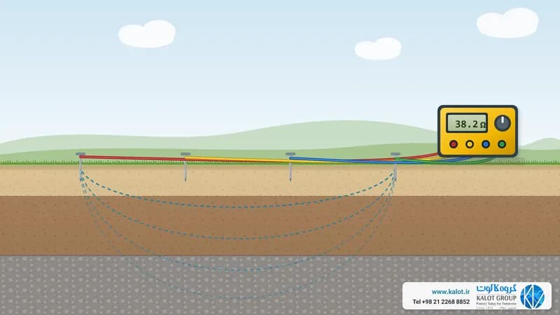
After construction, earth resistance is measured by the three-pole method, which we describe in measuring earth resistance. Earthing system testing and measurement and periodic inspection and testing are among the services we carry out on site.
What resistance does a foundation earth give?
Because the electrode and connected reinforcing bars cover almost the entire foundation area, the resistance of a foundation earth is usually lower than with other methods. BS 7430 (clause 8.5.8.6) says the underground metalwork of large structures often gives a lower resistance than any other method, with figures well below 1 ohm also being achieved. For an initial estimate, the ring and foundation electrode can be calculated like an earth grid; the formula and a worked example are in our formula for calculating earth electrode and earth pit resistance. The final figure is always set by measurement after installation.
Reference standards
- Iranian National Standard 23064 (first edition, 1400), Foundation earth electrode (substructure): planning, installation and documentation; a modified translation of DIN 18014:2014; download the standard as a PDF;
- DIN 18014:2023-06, earthing of buildings: planning, installation and documentation (replaces the 2014 edition);
- BS 7430:2026, code of practice for protective earthing of electrical installations, clauses 7.1 and 8.6;
- IEC 62305-3, protection of structures against lightning;
- EN 62561-1, EN 62561-2 and EN 62561-5, connection components, conductors and feed-throughs for earthing and lightning protection systems.
For projects in Iran, National Standard 23064, Topic Thirteen of the National Building Regulations and local rules are the main reference, and other standards are used alongside them.
Conclusion
A foundation earth is the simplest and most durable way to build a building's earthing system, provided it is installed correctly: a closed ring with mesh cells of at most 20 × 20 m, at least 5 cm of concrete cover, a firm connection to the reinforcing bars at least every 2 m, enough branches, and testing and recording before the pour. If the foundation is watertight or insulated, the electrode must be installed in the soil outside the foundation.
Send us your foundation drawing and the type of insulation in your building, and our specialists at KALOT Group will design the foundation earth bonding drawing and supply the round wire, tape, clamps, bonding plates and earth bars you need. For earthing and bonding system design, earthing system installation or an equipment quote, please contact us.