
Move your pointer over the image to zoom in
Complete Product Overview
KALOT down conductor wall stand-off base, model BPH 76
Order Code: BPH 76
Last updated:
The KALOT BPH 76 stand-off base holds and guides a down conductor on a building facade. It keeps the conductor on a defined route, at a physical distance from the wall surface, and leaves room to fit a suitable clamp and inspect the route. With a compatible clamp, either a tape or a round down conductor can be mounted on the base; clamps are separate parts and must be chosen to match the conductor's shape and size. The brass body is cast in one piece, and the arm is not welded to the foot plate. This gap is a mechanical installation distance and does not, by itself, mean the conductor is insulated or that a calculated electrical separation distance is met.
A tidy, inspectable conductor route
The base holds the down conductor on a defined route, at a physical distance from the wall surface. The clamp position is clear, and the conductor route and joints can be inspected.
Clamp choice to match tape or round conductors
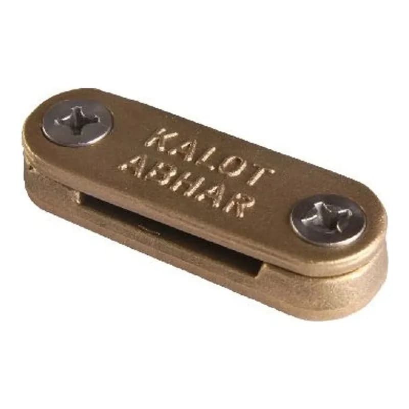
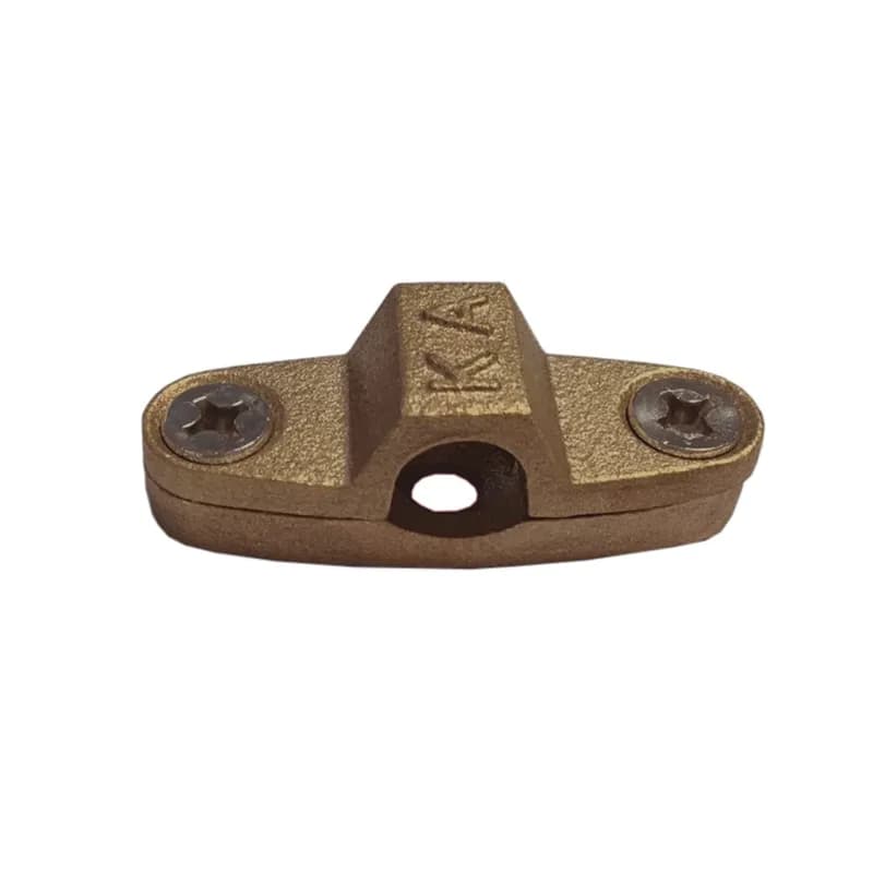
For tape, use the two-piece brass tape clamp (DC clamp, code DCC 253 or DCC 303), and for round conductors the two-piece brass conductor clamp (Heavy Duty, code HDCC), sized to the conductor. The clamps are separate parts and are not counted as part of the base; state their type and quantity in your enquiry.
One-piece brass construction with no welded joint
The diamond-shaped foot and the arm are cast from brass as one piece, with no weld where the arm meets the foot. The KALOT ABHAR lettering is raised on the foot.
Technical Product Information
Feature | Value |
|---|---|
Model / code | BPH 76 |
Section type | Down conductor stand-off and holder base |
Material | Brass |
Construction | Plate and arm cast in one piece, no weld at the joint (as stated by the manufacturer) |
Diamond-shaped foot | 63 × 42 mm, 7 mm thick |
Total height | 74 mm |
Arm diameter | 16 mm |
Arm head | M6-6H internal thread, 12 mm deep |
Mounting holes | Two Ø6.6 holes with Ø13 × 90° countersink |
Weight | 214 g |
Raised lettering | KALOT ABHAR on the foot |
Fixing the base to the wall | Two countersunk screws through the holes in the foot |
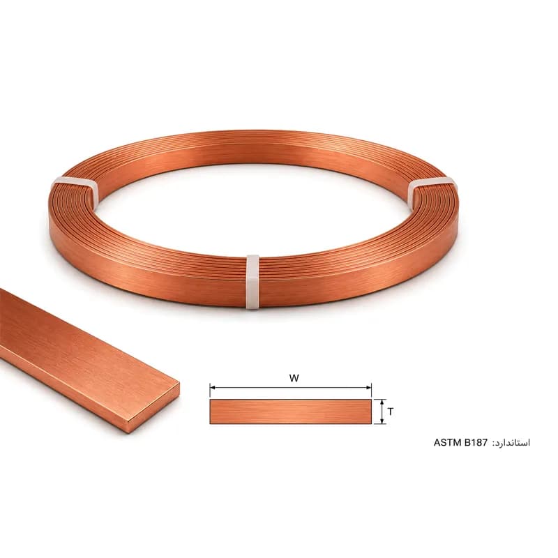
Conductor type in the catalogue application | Copper tape or round copper conductor, 50-70 mm² |
Conductor holding clamp | Separate part. Tape: DC tape clamp (DCC 253 / DCC 303). 50-70 mm² conductor: two-piece DC conductor clamp |
Ordering table
Order code | Material | Height (mm) | Foot (mm) | Clamp required | Order status |
|---|---|---|---|---|---|
BPH 76 | Brass | 74 | 63 × 42 | Select by conductor type and size | Price and availability on enquiry |
Click to view enlarged
The drawing is based on the KALOT Group manufacturing drawing: a 63×42 mm diamond-shaped foot, 7 thick, a Ø16 arm with a total height of 74 mm, an M6 internal thread 12 mm deep in the arm head, and two Ø6.6 holes with a 90-degree countersink for countersunk screws. With the 50-70 DC conductor clamp, the total distance from the back of the foot to the top of the clamp is 92 mm. These figures are mechanical dimensions and do not determine the design's electrical separation distance.
Click to view enlarged
Why and where
On some down conductor routes, the designer or installer needs the conductor held at a physical distance from the wall surface rather than fixed flat against the facade. The BPH 76 base attaches to the wall by its diamond-shaped foot and projecting arm, and a clamp on the arm head holds the conductor in its set position. The main role of the base is mechanical support and spacing; the continuous lightning current path runs through the down conductor itself.
Choosing the clamp
Tape conductor: KALOT DC tape clamp (DCC 253 or DCC 303, to match the tape). The clamp base is fastened with a screw through its centre hole to the threaded arm head, the tape lies on the base, and the cap is closed with two screws.
Round conductor: KALOT two-piece DC conductor clamp for 50 or 70 mm² conductor. The lower clamp piece is fastened to the arm head with one M6×10 countersunk screw through its centre hole, the conductor sits between the two pieces, and the upper piece is closed with two M6×10 screws. The total distance from the back of the foot to the top of the clamp is 92 mm.
This metal base is not an electrical insulator. The 74 mm height of the base (and 92 mm with the DC conductor clamp) is a mechanical dimension of the part. On its own, it neither defines the actual distance of the conductor from the facade nor confirms that the separation distance the design requires has been met; that distance is a matter for the design of the lightning protection system.
Common applications
- Securing a down conductor on a vertical facade route, where the design calls for installation at a distance from the wall surface.
- Creating a visible, tidy conductor route on a suitable substrate, together with the clamp selected for the conductor.
- Completing the down conductor installation set, alongside a clamp, screws and wall plugs suited to the substrate.
For special applications: on combustible facades, metal surfaces, in corrosive environments, or wherever safety distance from metal parts is a design matter, the connection details and the use of this conductive base must be confirmed separately. Do not present it as a substitute for an insulating base or an insulated down conductor system.
Short installation guide
- Set the conductor route and support points according to the installation drawing and the type of substrate.
- Fix the base firmly with countersunk screws through its two countersunk holes. The KALOT assembly drawing specifies M6×16 screws; choose the wall plug or anchor to suit the wall material.
- Fasten the conductor clamp with an M6 screw into the thread in the arm head.
- Lay the conductor continuously in the clamp without awkward twisting, then check that it is tight and the route is straight.
- Check the actual distance of the conductor from the surface, and the safety and maintenance details, against the project design.
Stand-off support holding the down conductor off the wall
Documents & Downloads
Catalogues & datasheets
- Technical specification sheet for the KALOT BPH 76 down conductor stand-off base (PDF, Persian)Language: Persian (opens in a new tab)
- Technical data sheet for the KALOT BPH 76 down conductor wall stand-off base (PDF, English)Language: English (opens in a new tab)
- Technical data sheet for the KALOT BPH 76 down conductor wall stand-off base (PDF, English)Language: English (opens in a new tab)
Drawings & schematics
Frequently Asked Questions
Does the lightning current have to pass through the base itself?
No. The base holds and spaces the conductor. The main path of the down conductor is the continuous tape held in the clamp. When installing on a metal surface, bonding or unintended contact is assessed according to the design.
Is this base insulated, and does it guarantee the electrical safety distance?
No. This part is metal. Do not treat its 74 mm height as the design safety distance or as the actual distance from the surface to the conductor.
Do the tape clamp and fixing screws come with the base?
Before placing your order, specify the accompanying items and the clamp model in the proforma invoice.
Does it suit every size of copper tape?
The width and thickness of tape that can be fitted depend on the clamp you select.
What are the main dimensions of the BPH 76 base?
A 63×42 mm diamond-shaped foot, 7 thick, a Ø16 arm and a total height of 74 mm. The arm head has an M6 internal thread 12 mm deep, and the part weighs 214 g.
Have a Technical Question?
KALOT Group's technical experts are ready to answer your questions about lightning rods and earthing systems.