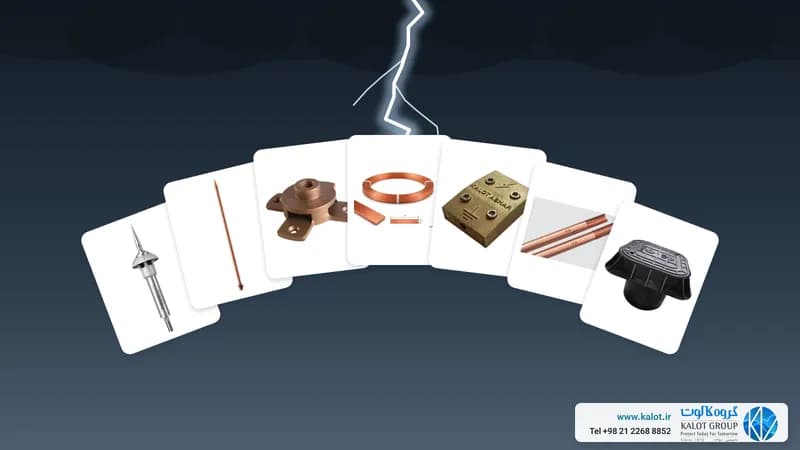
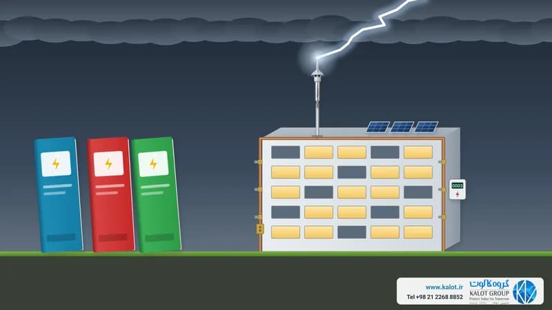
The short answer: a lightning protection system (LPS) is a set of components that intercepts the lightning current before it reaches the building, brings it down along a safe path and disperses it harmlessly into the earth. It has two parts: external protection, made up of the air-termination system (conventional air rod, mesh, suspended wire or ESE air terminal), the down conductor and the earthing system; and internal protection, made up of bonding, keeping the separation distance and surge protective devices (SPDs). If any one of these parts is wrongly chosen or poorly installed, the whole system is weakened.
In this guide, we at KALOT Group explain each part in plain language, show which component does which job and finish by reviewing the factors that shape the choice of system. For the full design process, from risk assessment to inspection, also read our article how to counter the destructive effects of lightning.
What is a lightning protection system?
Lightning is a current of tens of kiloamperes that flows in a few millionths of a second. If it hits an unprotected building, it finds its own way through the roof, pipes, electrical wiring or reinforcing bars, leaving behind fire, cracked concrete and brickwork, electric shock and burnt-out equipment. A lightning protection system decides this path in advance: it gives the lightning a safe place to strike and a short, controlled route to earth.
The main design reference is the international IEC 62305 series, and its third part, IEC 62305-3, defines the components of the external and internal systems. Alongside it, systems designed with ESE air terminals are installed to the French standard NF C 17-102; both methods are common in Iran and worldwide. The Safety Code for Earthing Systems (approved 1401) also defines the lightning protection system in four classes, as IEC 62305 does. We list all the references in lightning protection standards.
Components of the external protection system
External protection has three main components, linked like a chain: the air-termination system on the roof, the down conductors on the façade and the earthing system in the soil. The weakest link sets the quality of the whole chain.
1. Air-termination system (air terminal): where should the lightning strike?
The air-termination system is the part the lightning strikes. Its job is to make the strike land on a planned metal component rather than on the roof, walls or equipment. There are four common ways to build it, and many projects combine several of them:
- Conventional air rod (Franklin): a metal rod installed from a few tens of centimetres to a few metres above the roof, protecting the cone-shaped space beneath it. It suits chimneys, rooftop equipment, small roofs and pitched roofs. We offer conventional air rods in copper, nickel-chrome plated copper and stainless steel, with air rod bases for flat roofs, roof ridges and wall mounting.
- Mesh: a network of conductors laid across a flat roof, with mesh cells from 5×5 to 20×20 m depending on the protection class. It is economical for large industrial and commercial roofs and is usually installed with copper tape or galvanised steel round wire and connecting clamps.
- Suspended wire (catenary): a wire stretched between two or more masts above the structure, without touching the structure itself. It is used for fuel tanks, stores of flammable materials and other places where lightning current must not pass over the structure.
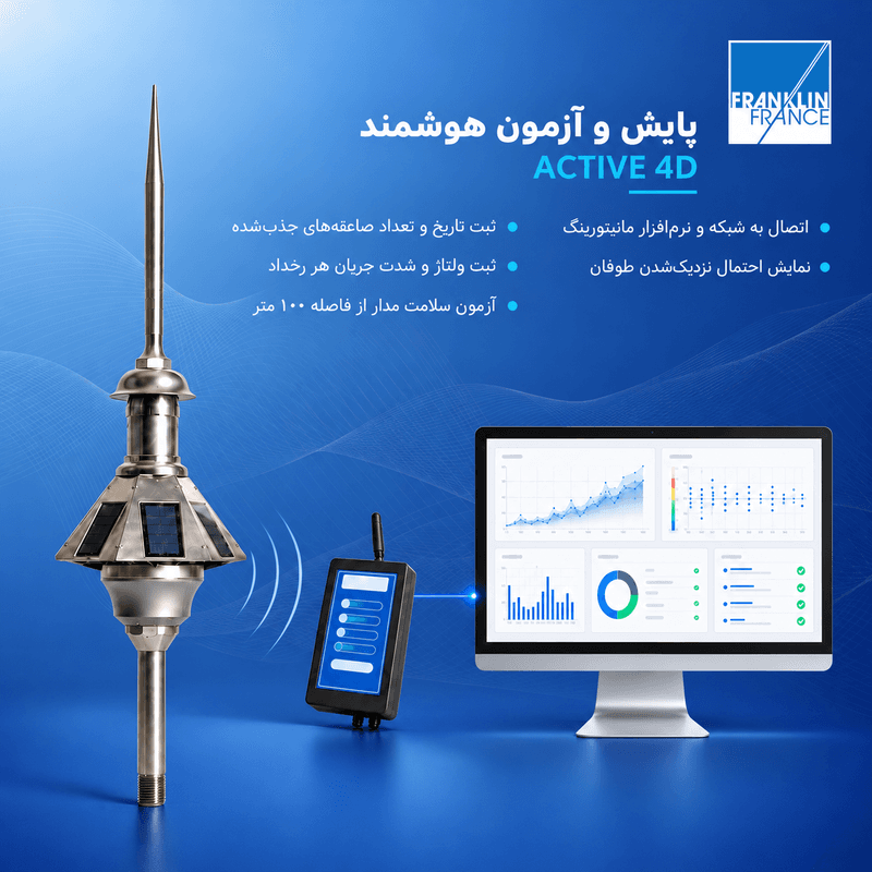
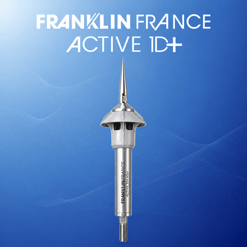
- ESE air terminal to NF C 17-102: an air terminal head mounted on a mast that launches an upward leader earlier than a conventional air rod of the same height. This time advantage is called ΔT, and the protection radius Rp is calculated from ΔT, the installation height and the protection level. A single ESE air terminal, with one mast and few down conductors, covers a wide area, making it a common and economical method for complexes, factories, open spaces and buildings whose roofs make a mesh difficult to install. We offer Franklin France ESE air terminals, including ACTIVE 1D+, ACTIVE 2D and ACTIVE 4D, with the telescopic mast and arched clamp. We explain the step-by-step design of this method in ESE air terminals and the NF C 17-102 standard and 25 points for installing to NF C 17-102.
Metal parts of the building itself can also act as a "natural" air-termination system, such as a metal roof, railings or a metal chimney, provided they are continuous and thick enough. For metal sheet that must not be pierced or overheated at the point of strike, IEC 62305-3 sets a thickness of at least 4 mm for steel, 5 mm for copper and 7 mm for aluminium.
In the IEC 62305-3 methods, the size of the air-termination system depends on the protection class. The table below shows the main values:
LPS class | Rolling sphere radius | Mesh cell size | Typical down conductor spacing |
|---|---|---|---|
I | 20 m | 5 × 5 m | 10 m |
II | 30 m | 10 × 10 m | 10 m |
III | 45 m | 15 × 15 m | 15 m |
IV | 60 m | 20 × 20 m | 20 m |
ESE air terminals also have four protection levels, I to IV, and the level sets the protection radius. We compare which method suits your project better in choosing the best air terminal: ESE and passive compared.
2. Down conductor: where should the current come down?
The down conductor carries lightning current from the air-termination system to the earthing system. The more conductors there are, the more the current is shared between them, and the lower the induced voltage and the risk of sparking. The main points:
- Number and spacing: IEC 62305-3 requires at least two down conductors, spread around the building and preferably placed at the corners. The typical spacing between them is about 10 m for Class I and II, about 15 m for Class III and about 20 m for Class IV. Under NF C 17-102, each ESE air terminal likewise has at least two down conductors, preferably installed on different façades.
- Route: short, straight and outside the building as far as possible, with no loops or sharp angles, because the impulse current of lightning builds up high voltage at tight bends.
- Material and cross-section: the standard sets the minimum cross-section according to the material; for copper tape it is 50 mm². Tape is preferred to round wire. Common options are copper tape, tinned copper tape, stainless steel earth tape, galvanised steel tape and bare copper conductor. You will find them all in the conductors category.
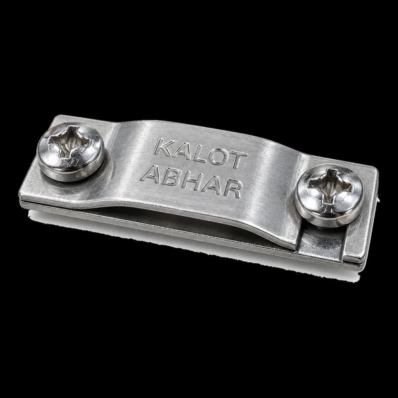
- Clamps: the conductor is fixed to the façade with closely spaced clamps, so that wind and the electrodynamic force of lightning cannot pull it away. Examples are the brass tape-to-wall clamp, the one-piece stainless steel tape clamp, the brass conductor-to-wall clamp and, for façades the conductor must not touch, the BPH 76 stand-off base. To join conductors together, use a two-way tape-to-tape clamp or a square four-way clamp.
- Natural conductors: a continuous metal frame or the interconnected reinforcing bars of a concrete building can also serve as down conductors, if their electrical continuity is verified.
Test joint (disconnector): why is it needed?
At the bottom of each down conductor, a little above ground level, a test joint is installed. Undoing its bolts separates the earthing system from the down conductor, so earth resistance can be measured on its own and the conductor's continuity tested. IEC 62305-3 calls for a test joint on each down conductor where it meets the earthing system, except for natural conductors connected to a foundation earth. For this job we offer the brass down conductor disconnector and the two-way conductor-to-tape clamp. In ESE systems, a lightning strike counter is usually also installed above the test joint, so that each strike is logged and an inspection follows.
3. Earthing system (earth termination): where should the current go?
The earthing system disperses lightning current into the soil without letting dangerous voltage build up on the surrounding ground or the building's installations. IEC 62305-3 defines two main arrangements, and the foundation electrode is a third route:
- Type A arrangement: a vertical or horizontal electrode is installed at the foot of each down conductor, with at least two electrodes. The required length depends on the protection class and soil resistivity. It is common for small buildings and earth rod systems and is usually installed with a copper-bonded earth rod or solid copper earth rod and an A-type clamp for connecting tape to earth rod.
- Type B arrangement: a closed ring around the building, with at least 80 percent of its length in contact with the soil, usually buried about half a metre deep and about one metre from the wall. It suits large buildings, rocky soil and buildings with a lot of electronic equipment, because it evens out the earth potential around the building.
- Foundation electrode: a steel conductor run inside the concrete foundation and connected to the reinforcing bars. In a new building this is the simplest and most durable route; we cover the installation details in foundation earthing.
About the 10-ohm figure: you often hear that 10 ohms is the maximum acceptable resistance and that every standard requires it. More precisely: IEC 62305-3 recommends a resistance below 10 ohms "where possible", but treats the shape and dimensions of the earthing system as the main criterion, so a system with enough electrode length and the right arrangement is acceptable even in high-resistivity soil. Under NF C 17-102, a resistance below 10 ohms is the target for the earthing of each down conductor. For the measurement and calculation methods, see measuring earth termination resistance, calculating earth electrode resistance and soil resistivity.
For underground connections, KALweld® exothermic welding creates a one-piece, durable joint. For access to the joint and for measurement, a polyethylene earth pit or concrete earth pit is installed, and in high-resistivity soils, GIM ground improvement material helps reach a lower resistance. The lightning earthing system is always connected to the building's electrical earthing system; separate earths create a dangerous potential difference during a strike.
Components of the internal protection system
External protection takes the lightning current to earth, but as that current passes, the voltage on the conductors and the building's earth rises for a moment. Internal protection prevents sparks between metal parts and damage to power and data installations. It has three main tools:
Lightning bonding
All metal parts entering the building, meaning water and gas pipes, cable sheaths, ducts and metal structures, are connected at their point of entry to a bonding bar (earth bar), so that they all share one potential and no spark can jump between them. To connect tape or conductor to pipes and structures, use a tape-to-pipe bonding clamp and a tape-to-metal plate bonding clamp. We give the details in bonding and equipotential bonding.
Separation distance
Lightning protection conductors must be kept far enough from cables, pipes and metal equipment inside or on the building; otherwise the lightning current jumps through the air or the wall. This distance comes from the formula s = ki × (kc / km) × l, where ki depends on the protection class (0.08 for Class I, 0.06 for Class II and 0.04 for Class III and IV), km on the material in the gap (1 for air and 0.5 for concrete and brick), kc on the share of current through each conductor, and l is the conductor length to the nearest bonding point. If this distance cannot be kept, the metal equipment is bonded to the conductor. A common example is an air conditioner or ventilation unit on the roof whose power cable enters the building.
Surge protective device (SPD)
Power and data cables entering the building cannot be connected directly to the bonding bar. Instead, they get a surge protective device (SPD), which conducts only during an overvoltage. In a building with a lightning protection system, a Type 1 SPD is required at the incoming panel, such as a Class 1 power SPD, three-phase, TNS or a Combined Class 1+2+3 power SPD, three-phase, TNS. Further SPDs are installed in the distribution boards and close to sensitive equipment, following IEC 62305-4 and the lightning protection zones (LPZ) concept. Browse all our power SPDs and data line SPDs, and read the full explanation in secondary lightning protection and types of SPD.
Summary table: each component, its job and the right parts
Component | Job | Suitable parts |
|---|---|---|
Air-termination system | Intercepts lightning at a planned point | |
Roof conductor and down conductor | Carry current from the roof to earth | |
Test joint and counter | Separate for measurement, log strikes | |
Earthing system | Disperses current into the soil | Copper-bonded earth rod, exothermic welding, earth inspection pit, ground improvement material |
Bonding | Brings metal parts to one potential | |
SPD | Limits overvoltage on cables |
See the full list of equipment for this system in lightning protection equipment and accessories, and all our products in lightning protection equipment.
Factors in choosing a lightning protection system
No ready-made system fits every building. These factors set the type and size of the system:
- Risk assessment and protection class: IEC 62305-2 shows whether protection is needed at all and whether its class should be I, II, III or IV. The lightning density in the region, the building's dimensions and use, the number of occupants and the value of the equipment all feed into this calculation.
- Shape, height and roof type: a large flat roof leans towards mesh, a pitched roof or chimney towards air rods, and a tall building or open site towards ESE air terminals or a combination of methods. On tall structures, side strikes to the façade are also taken into account.
- Building use and contents: stores of fuel, explosives or flammable materials call for stricter protection and sometimes a system separate from the structure (suspended wire or free-standing mast).
- Sensitive equipment: data centres, control rooms and hospitals need coordinated SPDs and LPZ zoning as well as external protection.
- Soil and ground space: soil resistivity and the space available decide between a Type A or B arrangement, the electrode length and the need for ground improvement material.
- Architecture and façade: on glass or stone façades, the conductor route, the use of the metal frame and stand-off bases are reviewed from the start of the design.
- Cost, installation and maintenance: the number of conductors and electrodes, access for inspection and the durability of parts in salty or polluted air all affect the total cost.
Our specialists carry out lightning risk assessments and, through lightning protection consulting and design, recommend the right method for your project, whether IEC 62305 or NF C 17-102. We also cover the latest changes to these standards in the new edition of the IEC 62305 series.
Inspection and maintenance
A lightning protection system changes over time and after every strike: clamps loosen, connections corrode and earth resistance rises. That is why, after installation, a visual inspection and a full test are carried out periodically and after every known strike, covering conductor continuity, the condition of clamps and test joints, and earth resistance measurement. On ESE air terminals, the health of the air terminal itself is also checked, using the remote tester for ACTIVE 2D. Periodic testing, inspection and maintenance and earthing system measurement are among our services.
Conclusion
A lightning protection system is much more than an air rod on the roof. The air-termination system (conventional air rod, mesh, suspended wire or ESE air terminal) intercepts the lightning, the down conductors bring it down along a short, safe path, the earthing system disperses the current into the soil, and bonding, the separation distance and SPDs prevent sparks and damage inside the building. The choice of method depends on the risk assessment, the shape of the building, the soil and the building's use.
At KALOT Group we offer every part of this system, from air terminals and conductors to earth rods, clamps and SPDs, and we also handle its installation and inspection. For advice or a quotation, please contact us.