Short answer: for calculating earth electrode resistance you need two things: the soil resistivity (ρ), measured on site, and the shape and size of the electrode. For a vertical earth rod, BS 7430:2026 gives the formula R = ρ/(2πL)·[ln(8L/d) − 1]. For example, a 3 m earth rod in soil with a resistivity of 100 ohm-metres has about 33 ohms; a 6 m earth rod brings this to about 19 ohms and four parallel earth rods to about 11 ohms.
In this guide, we at KALOT Group explain the BS 7430:2026 formulas in plain language for all the common electrodes (earth rod, pipe, plate, tape, ring, mesh, several parallel earth rods, an earth pit with ground improvement material, and special layouts such as triangles and crosses). A worked example shows which option performs best in practice, and we say what equipment each method needs.
What does earth electrode resistance mean?
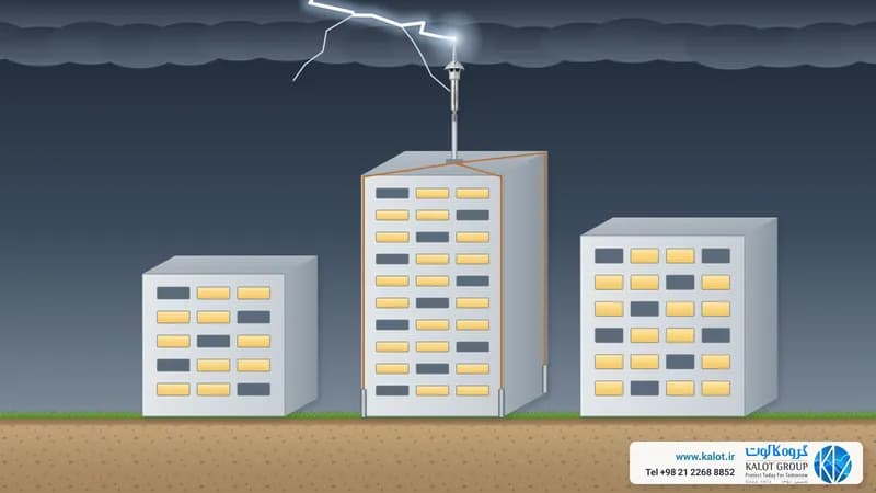
When fault current or lightning current reaches the earth electrode, it has to disperse through the soil. Soil behaves like a very large but not particularly good conductor. The resistance this path offers to the current is called earth electrode resistance, or in everyday terms "earth pit resistance", and it is measured in ohms (Ω). The lower this figure, the more easily the current flows to earth and the less dangerous voltage remains on equipment enclosures.
Under BS 7430 this resistance depends on three things: the soil resistivity, the shape and size of the electrode and how the system is connected to it. We explain what value each application needs in our article Earth resistance for different applications; this article is about how to calculate that figure.
Step one: measure the soil resistivity on site
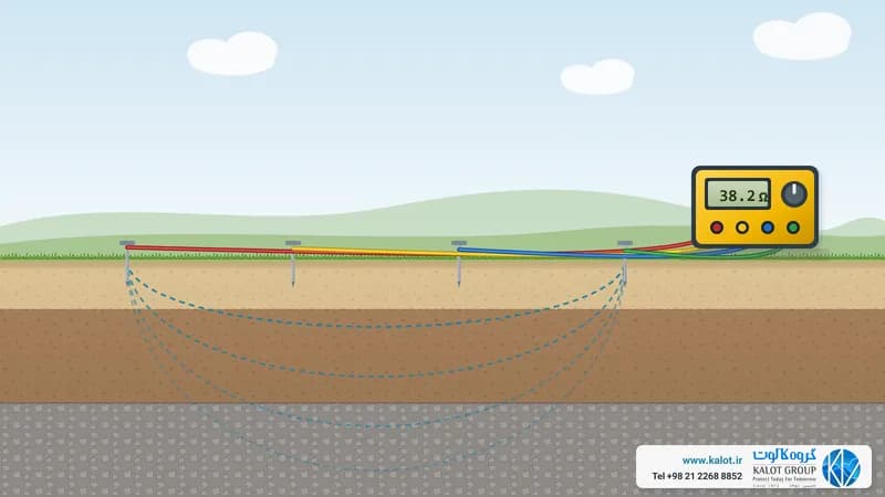
Every formula starts with ρ, and BS 7430 stresses that soil resistivity must be measured on site before design. Figures in textbook tables only show how difficult the job may be; they do not replace measurement. The usual approach is the Wenner four-pin method, described in What soil resistivity is and how it is measured. If you lack the instrument or the time, our specialists carry out soil resistivity measurement at your project site.
If you can choose the location: BS 7430 rates damp, clay soils as the best and dry sandy ground, stony or chalky ground and places where bedrock lies close to the surface as the least suitable. The soil around the electrode should be rammed and compacted, ideally with its moisture staying between 15 and 20 per cent. A stream bed is not a good location either, because running water washes away the soil's useful salts.
Designing and calculating an earth electrode in five steps
- Measure the soil resistivity at the project site, using the Wenner method.
- Set the target resistance according to the type of use, the regulations and the project design.
- Choose the electrode type and layout, then calculate with the formulas on this page.
- Install with suitable electrodes, conductors and connections, together with an inspection pit.
- Measure the resistance after installation; if the figure is above the target, the design is completed with more earth rods or conductors, or with ground improvement material.
Formulas for calculating earth electrode resistance to BS 7430
The formulas in this section come from clause 8.5 of BS 7430:2026. They all assume uniform soil and, according to the standard itself, their results usually match reality to within about ±15% when soil moisture is suitable. ln is the natural logarithm, found on any engineering calculator.
Symbols used in the formulas:
- R: electrode resistance to earth (ohms)
- ρ: soil resistivity (ohm-metres)
- L: electrode length in the soil (metres); for mesh and ring, the total conductor length
- d: earth rod diameter or pipe outside diameter; for tape, the tape width (metres)
- A: area of one face of the plate, or the area covered by the mesh or ring (square metres)
- h: burial depth of the horizontal tape or conductor (metres)
- n and s: number of earth rods and the spacing between them (metres)
- ρc and D: resistivity and diameter of the fill material column around the electrode
1. Vertical earth rod
The most common earth electrode is an earth rod driven vertically into the soil. The formula shows that earth rod length has the main effect and diameter very little; a 3 m earth rod with a 20 mm diameter has only about 4% less resistance than a 16 mm earth rod. That is why diameter is set mostly by the strength needed for driving, especially when earth rods are joined with couplings and taken to great depth.
For this method we manufacture the threaded copper-bonded earth rod (steel core with copper coating) with a brass coupling for extending the length, as well as the solid copper earth rod, stainless steel earth rod and galvanised earth rod. The choice of material depends on soil corrosivity, as we explain in our guide to choosing earth electrode material.
2. Pipe electrode
A driven metal pipe behaves electrically like an earth rod and is calculated with the same formula, using the outside diameter of the pipe. If the space around the pipe is filled with ground improvement material, use formula 8 below. We offer galvanised and stainless steel earth pipe for this method.
3. Earth plate
Because of its shape, an earth plate has higher resistance for its area than an earth rod or tape; BS 7430 says an earth rod or tape has much lower resistance than a plate with the same surface area. For example, a 1.2×1.2 m plate in 100 ohm-metre soil has about 37 ohms, more than a 3 m earth rod. A plate's resistance also falls with its dimensions, not in proportion to its area.
Under BS 7430, no plate should be larger than 1.2×1.2 m, it should have at least 600 mm of soil above it, several plates should be installed vertically and at least 2 m apart, and the connecting conductor should be fully insulated up to the disconnection point above ground. We offer the copper earth pit plate for projects that choose this method.
4. Horizontal tape or conductor
A tape or bare copper conductor buried horizontally in a trench is useful where a deep earth rod cannot be driven, such as in rocky ground. For example, 10 m of 30 mm tape at a depth of 60 cm in 100 ohm-metre soil has about 13 ohms. However, BS 7430 points out that lengthening a horizontal conductor has less effect beyond a certain point, and the resistance approaches a final value.
For this method we supply copper tape, bare copper conductor and galvanised tape; you will find every conductor in our conductors category.
5. Ring around the foundation
In buildings, a conductor laid all the way around the foundation or within the foundation concrete forms a large, lasting earth electrode. BS 7430 regards an electrode inside foundation concrete as a good approach: it needs no extra excavation, sits at a depth less affected by the seasons and makes good contact with the soil through the concrete. The standard gives no separate formula for a ring; for an initial estimate, you can use the mesh formula (formula 6) with the area inside the ring and its length. We cover the installation detail in Earthing systems based on foundation earthing.
6. Earthing mesh
In substations, power plants and large industrial sites, conductors are buried as a mesh under the whole area. The BS 7430 formula shows that the area under the mesh has the greatest effect: a 10×10 m mesh with 60 m of conductor in 100 ohm-metre soil has about 6 ohms. Conductor crossings are best made one piece with KALweld® conductor-to-conductor exothermic welding, so they do not loosen or corrode in the soil.
7. Several parallel earth rods
When one earth rod is not enough, we drive several in a line and join them with a conductor. If the earth rods are too close, the "area" of each overlaps the next and the result falls short of expectations; the factor λ in the formula accounts for this effect. In 100 ohm-metre soil, two 3 m earth rods spaced 3 m apart give about 19 ohms and four give about 11 ohms. Under BS 7430, for a 3 m earth rod there is little gain in spacing beyond about 10 m.
To connect earth rods to the conductor, we manufacture the G-type clamp for connecting conductor to earth rod and the A-type clamp for connecting tape to earth rod. For a permanent connection under the soil, conductor-to-earth rod exothermic welding is the usual choice.
8. Earth pit and electrode in ground improvement material
In high-resistivity soils, the space around the earth rod is filled with a low-resistance material. The BS 7430 formula for this case shows that the lower the material's resistivity (ρc) and the wider the fill column (D), the lower the total resistance. BS 7430 accepts mortars blended with conductive materials such as graphite or carbon for filling around earth rods and tapes, and does not recommend filling with coke breeze, fly ash, sand and gravel or coarse aggregate, because of corrosion or high resistance. In the view of this standard, pouring chemicals into the soil is not a long-term solution either.
We manufacture the ground improvement materials GIM, GIM Light and ECO GIM for exactly this job. We explain how to calculate resistance with them in Earth termination resistance calculations when using ground improvement material. Place the top of the earth rod inside a polyethylene earth pit so it stays accessible for inspection and measurement.
9. Special layouts: triangle, square, L, star, cross and parallel tapes
For places where earth rods or tape cannot be set in a straight line, BS 7430 also gives formulas for several other common layouts (clauses 8.5.5 and 8.5.8):
- Three earth rods at the corners of a triangle: in 100 ohm-metre soil, three 3 m earth rods with 3 m sides give about 14.7 ohms; almost the same as three earth rods in a line (about 14.1 ohms), but in a more compact space.
- Earth rods around the perimeter of a square: for multiple earth pits around a facility; for example, 8 earth rods of 3 m (three on each side) spaced 3 m apart give about 7.2 ohms. The factor λ for this layout is given in Table 3 of the standard.
- L, star and cross horizontal conductors: the same tape formula, with a different factor κ for each shape. For equal total length, a straight run is slightly better; for example, 40 m of tape in a straight line gives about 4.4 ohms and in a 4×10 m cross about 5.1 ohms. These shapes are useful when there is no room for a long trench.
- Several parallel tapes joined at one end: the resistance of one tape is multiplied by a factor F, which depends on the number of tapes and the ratio of spacing to length (s/L).
Worked example: which option is best in 100 ohm-metre soil?
To make the formulas tangible, we have calculated every option for uniform soil with a resistivity of 100 ohm-metres (earth rod diameter 16 mm):
Electrode arrangement | Calculated resistance (ohms) |
|---|---|
1.2×1.2 m earth plate | 36.9 |
One 3 m earth rod | 33.5 |
Two 3 m earth rods spaced 3 m apart | 19.4 |
One 6 m earth rod (two 3 m earth rods with a coupling) | 18.6 |
10 m of 30 mm tape at a depth of 0.6 m | 13.2 |
One 9 m earth rod | 13.1 |
Four 3 m earth rods spaced 3 m apart | 11.3 |
10×10 m mesh with 60 m of conductor | 6.1 |
What this example tells us:
- A 6 m earth rod gives almost the same result as two 3 m earth rods spaced 3 m apart; if the ground allows deep driving, the longer earth rod takes up less space and has fewer connections.
- An earth plate, despite its large area, is no better than a 3 m earth rod.
- To reach just a few ohms, you need several earth rods, tape and mesh, or better soil around the electrode.
Calculating earth pit depth
One of the most common questions is "how deep should an earth pit be?" The earth rod formula itself gives the answer: enter the soil resistivity and find the length that reaches the target resistance. The left-hand chart in the figure above shows this for 100 ohm-metre soil: 1.5 m about 60 ohms, 3 m about 34, 6 m about 19, 9 m about 13 and 12 m about 10 ohms. So the deeper we go, the more slowly the resistance falls, and beyond a certain point adding another earth rod or tape works better than going deeper.
These figures are for uniform soil. In practice soil is layered and deeper layers are often damper, so a deep earth rod may perform even better than calculated. Wenner measurements at several different spacings show this in advance.
Why does the calculated figure differ from the measured one?
- Soil is not uniform: the formulas assume a single resistivity for all the soil, but real soil has different layers.
- Moisture and season: resistance is higher in the dry season. Because of frost, BS 7430 does not count as effective any part of the electrode less than half a metre below ground.
- Electrode contact with the soil: loose soil or voids around the electrode raise the resistance; the soil around the electrode should be rammed and compacted.
- Connections: a loose or rusty connection between the conductor and the earth rod adds extra resistance to the path.
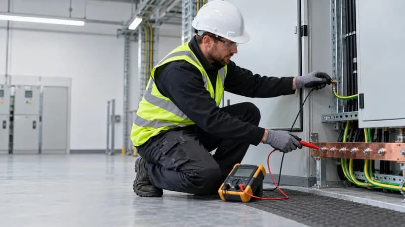
That is why resistance must always be measured after installation using the three-pole method; we describe how in Measuring earth resistance with the three-pole method. Earthing system testing and measurement is also one of the services we carry out at project sites.
How can you lower earth electrode resistance?
- Make the electrode longer: using a coupling, drive several copper-bonded earth rods one after another until you reach damp layers.
- Add more earth rods and do not drive them too close together: under IEEE 142, a second earth rod only comes close to halving the resistance when the two are several rod lengths apart, and under BS 7430, for a 3 m earth rod there is little gain in spacing beyond about 10 m.
- Add a horizontal conductor or mesh, especially in rocky ground where deep driving is not possible.
- Fill around the electrode with a suitable material: GIM ground improvement material.
- Make connections permanent and reliable: with KALweld® exothermic welding or suitable earthing clamps, and place the top of the electrode in an earth inspection pit.
Quick calculation with the KALOT earthing calculator
If you would rather not work through the formulas by hand, try our earthing calculator: enter the soil resistivity and electrode type to see the estimated resistance, with a comparison with and without GIM ground improvement material. The calculator's result is an initial estimate, and for each project our specialists review the design closely and recalculate it.
Reference standard
The formulas and recommendations in this article come from the British Standard BS 7430:2026 (code of practice for protective earthing of electrical installations), especially its clause 8.5. For projects inside Iran, Topic Thirteen of the National Building Regulations and local rules are the main reference, and this standard is used alongside them.
Footnote (other standards): other respected standards also offer formulas or methods for calculating earth electrode resistance. This is not the place to explain them in full, so we only summarise them. IEEE Std 80 is dedicated to high-voltage substation earthing meshes and has more precise formulas that also take account of burial depth and combined mesh and earth rods, used mainly to control touch and step voltage. IEEE Std 142 has a table of approximate formulas for various electrode shapes and recommends software for large designs. BS EN 50522 gives charts and a simple approximate relation for meshes in high-voltage installations. IEC 62305-3, for lightning protection earthing, sets Type A and Type B arrangements and minimum electrode length according to protection class and soil resistivity, rather than a resistance formula. The single earth rod formula has the same root in all these references and gives close results.
Conclusion
Calculating earth electrode resistance starts with measuring soil resistivity and continues with the right formula for each electrode. Earth rod length matters more than diameter, an earth plate is less efficient for its area, and reaching low resistances takes several earth rods, tape, mesh or ground improvement material used together. The formulas are for design; the final figure always comes from measurement after installation.
If you send us your soil measurement results, site drawing and target resistance, our specialists at KALOT Group will calculate the right electrode layout and recommend and provide the equipment needed, from earth rods and conductors to ground improvement material and exothermic welding. For earthing system design, earthing system installation or an equipment quotation, please contact us.