Short answer: lightning protection zones (LPZ) are a method in IEC 62305-4 that divides the space outside and inside a building into zones according to the severity of lightning effects: LPZ 0A and LPZ 0B outside the building, and LPZ 1, LPZ 2 and LPZ 3 inside it. At the boundary of each zone, all lines and metal parts are bonded, the right SPD for that boundary is installed on the power and data lines, and where needed spatial shielding weakens the magnetic field. In this way the lightning energy is reduced step by step rather than all at once, until it reaches a level that sensitive equipment can withstand.
What are the LPZ zones?
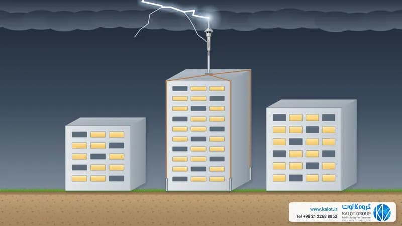
- LPZ 0A: outside the building and exposed to direct lightning strikes; both the full lightning current and its full magnetic field reach this zone.
- LPZ 0B: outside the building but sheltered by the air terminal, so there is no direct strike; it still has the full magnetic field and induced currents (choosing an air terminal).
- LPZ 1: inside the building. The lightning current is limited by sharing between conductors and the SPDs at the entrance, and the building's metal structure weakens the field to some extent.
- LPZ 2: a zone inside LPZ 1, such as a shielded equipment room or server room, with additional SPDs and shielding.
- LPZ 3 and above: inside a panel, rack or the equipment's own metal casing, with an SPD close to the equipment or a filter.
Not every building needs all of these zones; the number of zones depends on how sensitive the equipment is and on the result of the risk assessment.
What do we do at each zone boundary?
Boundary | Bonding | SPD on power and data lines | Shielding |
|---|---|---|---|
LPZ 0 to LPZ 1 | All incoming pipes, cables and metal parts to the bonding bar | Type 1 (T1) or combined; on lines carrying only induced voltage, Type 2 in some cases | Bonded concrete reinforcing bars, steel frame and metal facade |
LPZ 1 to LPZ 2 | Bonding bar at the room entrance | Type 2 (T2) | Room shielding, metal rack, metal cable tray |
LPZ 2 to LPZ 3 | Bonding of the equipment casing | Type 3 (T3), socket-type SPD or filter | Metal casing of the panel or device |
SPDs at consecutive boundaries must be coordinated so that each takes its share of the energy; we explain this coordination and the difference between Type 1, 2 and 3 SPDs in types of SPD. For power we offer power SPDs such as the combined Class 1+2+3 three-phase TNS power SPD, and for data and telecommunication lines our data line SPDs.
Spatial shielding and cable routing: protection against the lightning field
An SPD only catches overvoltage that arrives along the lines. The lightning magnetic field, whether from a strike on the building itself or a nearby strike, induces voltage in cable loops inside the building even without an incoming line. IEC 62305-4 states clearly that a coordinated SPD system on its own protects only against conducted overvoltages, not against the field. For the field, these measures are needed:
- Grid shielding: concrete reinforcing bars, steel frame, metal roof and facade, bonded at several points to one another and to the foundation earth electrode, make a low-cost shield; the finer the grid mesh, the weaker the field inside.
- Small cable loop: power and data cables linking two pieces of equipment should run side by side along the same route so that the induction loop stays small.
- Cable trays and shields: metal cable trays and cable shields should be connected to bonding at both ends.
- Distance from the shield: do not place sensitive equipment hard against a shield wall or down conductor; the field is stronger close to the shield.
This bonding is carried out with copper tape, earthing clamps and exothermic welding joints (bonding and equipotentialisation).
Designing lightning protection zones in a few steps
- Assess the lightning risk and set the protection level (IEC 62305-2).
- Define the LPZ zones according to where the sensitive equipment sits and how the incoming lines run.
- Bond all metal parts and lines at the boundary of each zone.
- Select coordinated SPDs for each boundary, on power and on all data, telecommunication and camera lines.
- Spatial shielding and cable routing.
- Periodic inspection and testing of bonding, the earthing system and SPDs.
We cover the overall picture of internal protection in secondary lightning protection and SPDs, the four measures of IEC 62305-4 in earthing, bonding and EMC, and lightning effects in types of lightning effects. We carry out lightning risk assessment, overvoltage protection design and SPD selection and lightning protection system design. For advice, send our specialists the building drawing and the location of your sensitive equipment, or get in touch through our contact page.