What is soil resistivity?
Short answer: soil resistivity (ρ) is the electrical resistance of a one-metre cube of soil between two opposite faces, and its unit is the ohm-metre (Ω·m). One ohm-metre equals 100 ohm-centimetres. ρ depends on the soil type, moisture, temperature, compaction and dissolved salts, and it ranges from a few ohm-metres in alluvium and wet clay to 1000 ohm-metres and above in rock.
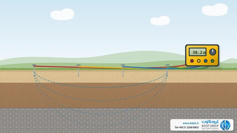
Unlike the resistance of an electrode, resistivity is a property of the soil itself. The resistance of any electrode is directly proportional to the ρ of the soil. The general formula is ρ = R · A / L, where R is the resistance, A the cross-section and L the length of the sample. In field measurement by the Wenner method, ρ = 2π · a · R, where a is the electrode spacing and R is the measured resistance (measuring soil resistivity).
Soil resistivity table
The table below is from BS 7430:2026 (Table 2). The figures are for initial estimates only and do not replace on-site measurement. The value depends on rainfall and the groundwater level. All figures are in ohm-metres.
Soil or rock type | Probable value | Normal and high rainfall (over 500 mm a year) | Low rainfall and desert (under 250 mm) | Saline groundwater |
|---|---|---|---|---|
Alluvium and light clays | 5 | Depends on the water table | Depends on the water table | 1 to 5 |
Clay (excluding alluvium) | 10 | 5 to 20 | 10 to 100 | 1 to 5 |
Marl | 20 | 10 to 30 | 50 to 300 | Not specified |
Porous limestone (such as chalk) | 50 | 30 to 100 | Not specified | Not specified |
Porous sandstone and clay shale | 100 | 30 to 300 | Not specified | Not specified |
Quartzite, dense and crystalline limestone, marble | 300 | 100 to 1000 | Not specified | Not specified |
Clay slate and slaty shale | 1000 | 300 to 3000 | 1000 and above | 30 to 100 |
Granite | 1000 | Not specified | Not specified | Not specified |
Fissile shale, schist, gneiss and igneous rocks | 2000 | 1000 and above | Not specified | Not specified |
The second table is from IEEE 142-2007 (Table 4-2). It names soils by their standard soil classification (USCS) and, for each, also gives the resistance of a single 3 m earth rod with a 16 mm diameter:
Soil type (USCS class) | Resistivity (ohm-metres) | Resistance of a 3 m earth rod (ohms) |
|---|---|---|
Well-graded gravel and gravel-sand mix (GW) | 600 to 1000 | 180 to 300 |
Poorly graded gravel (GP) | 1000 to 2500 | 300 to 750 |
Clayey gravel and gravel, sand and clay mix (GC) | 200 to 400 | 60 to 120 |
Silty sand (SM) | 100 to 500 | 30 to 150 |
Clayey sand (SC) | 50 to 200 | 15 to 60 |
Fine silty or clayey sand of low plasticity (ML) | 30 to 80 | 9 to 24 |
Fine sandy soil or elastic silt (MH) | 80 to 300 | 24 to 90 |
Gravelly, sandy or silty clay and lean clay (CL) | 25 to 60 | 17 to 18 |
Inorganic clay of high plasticity (CH) | 10 to 55 | 3 to 16 |
The figures for clay depend heavily on moisture. In high-resistivity soils such as dry sand and rock, reaching the permitted resistance with one or two simple electrodes is difficult, and a ground improvement material, a deeper electrode or an electrode network becomes necessary.
Factors that affect soil resistivity
- Moisture: current in soil travels mostly through water and the salts dissolved in it. According to IEEE 142, the resistivity of red clay is about 80 ohm-metres at 22 percent moisture and reaches about 1800 ohm-metres at 10 percent. Below about 15 percent moisture, resistivity climbs quickly (is soil moisture a key factor?).
- Temperature and frost: as soil cools, its resistivity rises slightly. But once the water freezes, it multiplies: in a sandy loam, from about 100 ohm-metres at zero degrees with water, to about 300 ohm-metres with ice and about 700 ohm-metres at minus 5 degrees. That is why BS 7430 does not count the part of an electrode less than 0.5 m below ground as effective.
- Salts and dissolved minerals: the more salt dissolved in the soil water, the lower the resistivity, as with the soils near saline groundwater in the table above.
- Compaction: compacted soil conducts better than loose soil, so the soil around the electrode should be well tamped.
- Layering: soil is almost never uniform, and deeper layers can have very different resistivity. Measuring at different spacings reveals these layers.
Soil resistivity measurement methods
- Wenner four-point method: the most widely used method. Four electrodes are driven in a line at equal spacing a, and ρ = 2π · a · R is calculated.
- Schlumberger method: suited to investigating deeper layers with less moving of the electrodes.
These methods are covered in IEEE 81 and BS 7430. We set out the steps, electrode spacing and common field errors in our soil resistivity measurement guide and earth terminal resistance measurement. We also carry out soil resistivity measurement with a full report.
Why soil resistivity matters in earthing
- Setting the size, number and layout of earth electrodes (electrode resistance formulas).
- Choosing the right way to lower the earthing system resistance: a longer electrode, more electrodes or a ground improvement material.
- Predicting how earth resistance will change in dry and cold seasons.
- Designing a safe and economical protective system (specifying the protective earthing system).
Using ground improvement materials
When soil resistivity is very high, as in rocky ground or dry sand, even large electrodes may not reach the target resistance. In these conditions a standard ground improvement material makes the soil around the electrode conductive and stable. Carbon-based materials, which stay stable over time, are among the best categories of these materials. GIM is KALOT's carbon-based ground improvement material, used on many industrial and building projects. We show with a calculation how far the material lowers resistance in why ground improvement materials help. For advice, send our specialists your soil measurement results or reach us through our contact page.