
Earthing and Bonding System Design and Consultancy
At KALOT Group we design earthing and bonding systems around the supply earthing arrangement, the fault current paths, the electrical properties of the soil and the operating needs of the installation. Our aim is to limit dangerous potential differences, keep protective paths continuous, and make sure earthing and bonding work in step with the protective devices.
We choose the design references to suit the type of installation, the applicable regulations and the requirements of each project.
Our earthing and bonding design services
- Design basis: We review the supply earthing arrangement, power sources, operating modes, earth fault current and its disconnection time. We also analyse soil resistivity data, site conditions and the seasonal changes that affect earthing performance, then set the safety and performance criteria for the design.
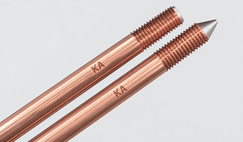
- Electrodes and earth grids: We specify the type, size and layout of the electrodes and calculate the earth resistance or impedance. We also assess foundation earth electrodes and natural components of the structure, once their technical suitability and electrical continuity are confirmed.
- Bonding and protective paths: We define the main earthing terminal, the routes of the protective conductors, and the main and supplementary protective bonding connections. We identify the conductive parts to be bonded and specify how their electrical continuity will be maintained.
- Safety checks and protection coordination: We check that the fault current path is adequate and that the protective devices will operate as required, including automatic disconnection of supply in low-voltage installations. Depending on the installation, we also assess earth potential rise, touch and step voltages, and the risk of transferred potentials.
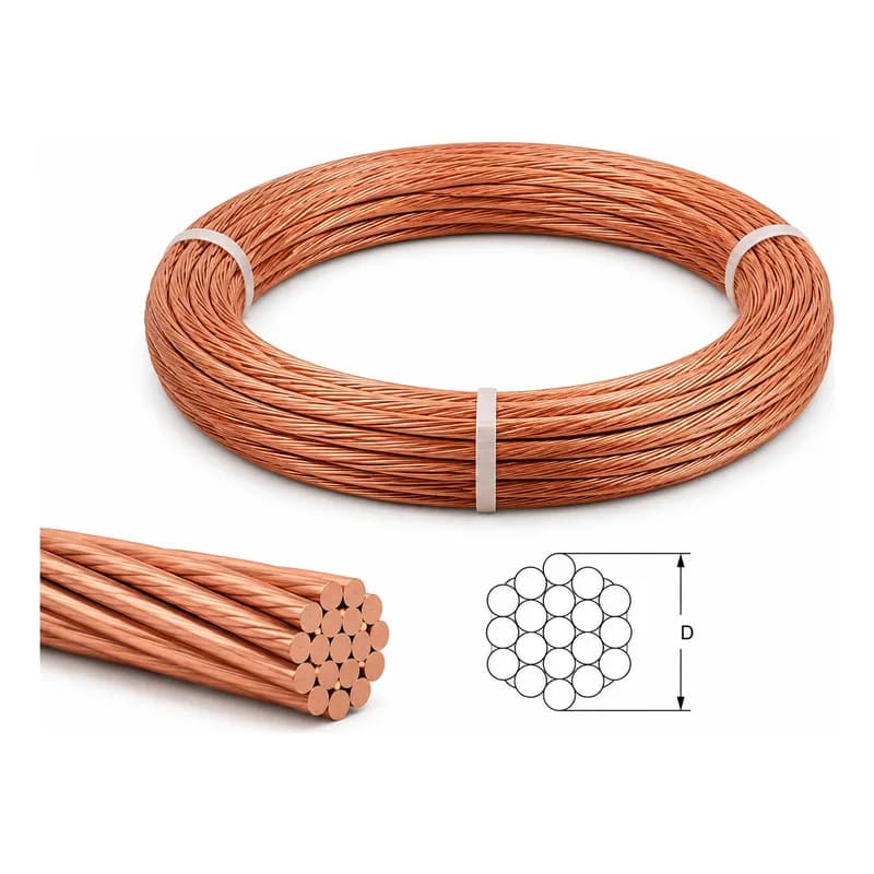
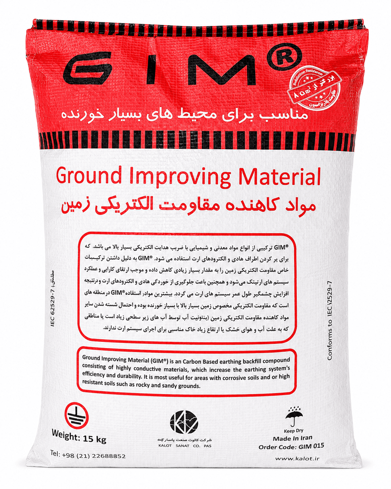
- Conductors, connections and materials: We set conductor materials and cross-sections, and specify electrodes and connections according to thermal withstand, mechanical requirements and site conditions. We also check metal compatibility, corrosion and the durability of buried components.
- Specialist coordination and documentation: We address the relationship between protective and functional earthing, and the earthing and bonding needs of lightning protection, sensitive equipment, static electricity control and potentially explosive atmospheres. We prepare calculations, drawings, construction details and test and acceptance criteria, and we recommend improvements for existing designs and systems.
Related articles and services
The key input for this design comes from soil resistivity measurement. To learn more, read our guides to the TN-S, TN-C, TN-C-S, TT and IT earthing systems and the IT earthing system.
You will find the components for your design in our earthing and bonding products. Press the “Request a Technical Consultation” button and our engineers will contact you to discuss your project.
Have a Technical Question?
KALOT Group's technical experts are ready to answer your questions about lightning rods and earthing systems.