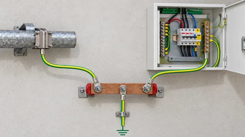
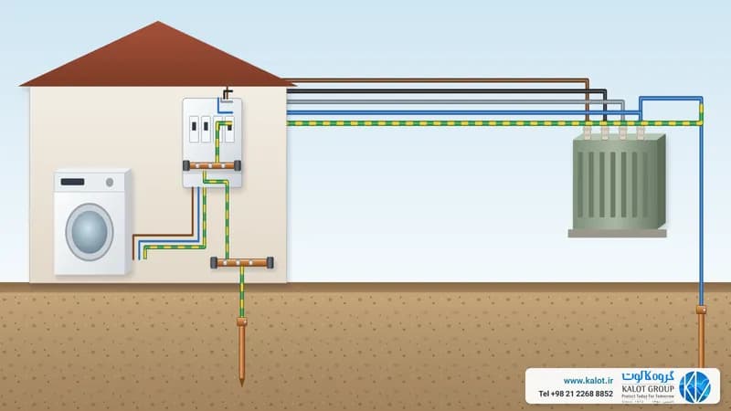
An electrical continuity test checks whether there is a reliable conductive path between two points that should be electrically connected. In electrical installations, the most important example is the path of the protective conductor (PE) and protective bonding from the main earthing terminal to the metal enclosures of equipment. The test is usually done by injecting a small current and measuring the resistance of that path; the reading is then compared with the conductor's length, material and cross-section, the number of joints and the design criterion.
This test is part of the initial and periodic verification of low-voltage installations. IEC 60364-6 sets out the framework for verifying installations, and IEC 61557-4 covers the requirements for instruments that measure the resistance of earth connections and equipotential bonding.
If you would first like to understand the connection paths themselves, our KALOT guide to bonding and equipotential bonding in earthing is a good place to start.
Why is a continuity test needed?
If the connection between the enclosure of a panel, machine or metal structure and the protective path is broken or loose, the enclosure may become dangerous during an insulation fault and the designed protection may not work as intended. Good continuity is one of the preconditions for the fault current path and for equipotential bonding; however, passing this test alone does not prove the safety of the whole system or timely disconnection by the protective device. That requires complementary tests and calculations in line with the design and the regulations. The IET guidance on protective conductors explains the role of the protective path when a fault occurs.
Faults this test can reveal include: a broken conductor, a loose termination, a slack clamp, corrosion or dirt at the contact point, a poor busbar connection and unintended changes to the bonding path. To judge the quality of a connection, the measured value should be read together with a physical inspection.
Continuity versus earth pit resistance and insulation resistance
Test | Key question | Example measurement path |
|---|---|---|
Protective continuity | Is there a conductive path from point A to B, and is its resistance in line with the design? | Main earthing terminal to the panel enclosure |
Earth electrode resistance | What is the resistance between the set of electrodes and the general mass of earth? | Earth electrode to reference earth, using a suitable method |
Insulation resistance | How well does the insulation between different conductors, or between a conductor and earth, block current? | Phase to earth or between live conductors |
So “an earth pit with good resistance” does not necessarily mean the PE conductor is sound all the way to every piece of equipment; equally, good continuity between two points says nothing about the earth electrode resistance. This distinction is decisive when choosing the instrument, the test method and the final report. For example, the IET treats the continuity test of a bonding conductor as recording the resistance of that conductor.
Where is the test carried out?
- Switchboards and distribution networks: between the main earthing terminal, the PE bars of panels, doors, enclosures and the end points of circuit protective conductors.
- Industrial machinery: between the machine's protective earth terminal and accessible metal parts, within that machine's own test programme. IEC 60204-1 covers the requirements for the electrical equipment of machines and protective bonding.
- Building and industrial bonding and earthing systems: connections of metal structures, cable trays, pipework and equipment according to the bonding drawing. Not every metal part necessarily needs bonding; the designer and the project standard decide.
- Lightning protection: continuity of the paths and testable joints in the lightning protection system, in line with the design and inspection plan. IEC 62305-3:2024 covers the design, installation, inspection and maintenance of an LPS.
- After installation, repair or alteration: at initial handover, after replacing a joint or conductor, after mechanical damage or corrosion, and at periodic inspections whose interval is set by risk and operating conditions. The IET stresses that the inspection interval depends on the type and condition of the installation.
What instruments and tools are needed?
- A continuity tester or multifunction installation tester able to measure low resistance over a suitable range. For testing protective and bonding conductors, compliance with IEC 61557-4 is a useful selection criterion. Instruments with a test current of 200 mA are common in this application; the IET guidance example mentions a range of 4 to 24 V and a current of 200 mA. These figures should not be applied to every application without checking the project method and standard.
- Suitable leads, probes and clips, including a long lead for measuring from the main earthing terminal to distant points. Before measuring, the lead resistance should be compensated using the instrument's nulling function.
- A four-wire (Kelvin) milliohmmeter when the work calls for the very low resistance of a specific joint, separating out the test lead resistance or higher accuracy. The four-wire method reduces the effect of lead resistance, but it does not by itself solve the parallel path problem. Technical note on four-wire measurement, note on parallel paths.
- A suitable voltage detector to prove the circuit is dead and isolation and lock-off equipment, together with the circuit drawing, a results form, and the instrument details and calibration. A continuity tester is no substitute for a tool that proves dead. HSE guidance.
Choosing an instrument: the continuity beeper on a general multimeter is useful for finding a complete break, but “it beeped” is not, on its own, a quantitative and valid record of the protective path resistance. The instrument, accuracy, test current and method must suit the purpose of the measurement.
Figure 2: The green/yellow path is the protective conductor under test. The dashed orange path is an example of a possible parallel path that can give an apparently good result even when the main connection is faulty.
Recommended test steps
1. Define the scope. Mark on the drawing which two points, which conductor and which joint are to be measured. A result without an identified start and end point cannot be traced.
2. Make it safe. A competent person identifies the supply sources, isolates the circuit and locks it off where needed, then proves it dead at the point of work with a suitable tool. Standby supplies, stored energy and adjacent sections also call for decisions suited to the site. HSE: safe working and proving dead.
3. Carry out a visual inspection. Check the contact surfaces, tightness of joints, corrosion, broken conductors and any possible parallel paths. Do not disconnect any protective conductor to separate paths without a safety assessment and an approved work method.
4. Prepare the instrument. Check the instrument and probes are sound and suitable, null or compensate the test leads, and record the method and test current.
5. Measure. One probe goes on a defined reference, usually the main earthing terminal (MET), and the other on a clean, conductive end point. Read the value once it has settled; if the result looks doubtful, improve the contact point and repeat the measurement following a fault-finding logic.
6. Interpret and document. Record the value in Ω, the path details, method, instrument, date, circuit status, the project acceptance criterion and the outcome. Paths with many joints or unexpected results need further investigation.
What is an acceptable value?
A fixed, universal number such as “every path must be below 1 ohm” is not a valid criterion for this test. The expected resistance depends on the conductor's length, material and cross-section, the temperature and the resistance of the joints. Even a very low value may not prove the intended conductor is sound if a parallel path is present. In its test report forms, the IET also notes that some readings become meaningless when parallel return paths exist. IET model forms.
For a uniform conductor, a first estimate comes from R ≈ ρL/A, where ρ is the resistivity of the material, L the length and A the cross-section. Joint resistance and real site conditions must be considered separately. The final acceptance criterion should be set in the design specification, the applicable standard, the manufacturer's instructions or the project's approved method statement.
Advantages and limitations of the test
Advantages: quick detection of a break or weak joint, a value that can be recorded and compared at later inspections, and support for technical handover and locating faults in the bonding network. Doing it before commissioning or after a repair can stop a hidden fault from remaining in the protective path.
Limitations and practical cost: it usually needs coordination to isolate the section under test; results are sensitive to probe contact and lead compensation; parallel metal paths can hide a fault; and a low-current test alone does not prove how a joint behaves under a real fault current or a lightning strike. So the continuity test should sit alongside inspection, calculations and the other tests the project requires. Note on parallel paths, IEC 62305-3 on LPS inspection and maintenance.
Related KALOT services and equipment
Our KALOT earthing system testing and earth resistance measurement service also includes continuity testing of protective and bonding conductors. At KALOT Group we set the measurement points to suit the drawings and site conditions and record the results in a technical report. For ongoing monitoring, see our periodic inspection and maintenance service.
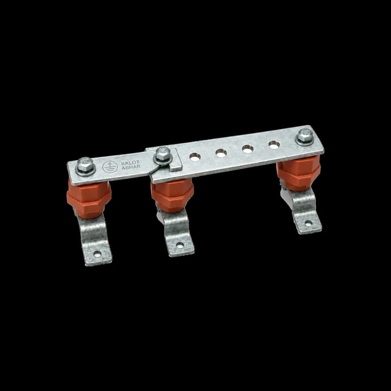
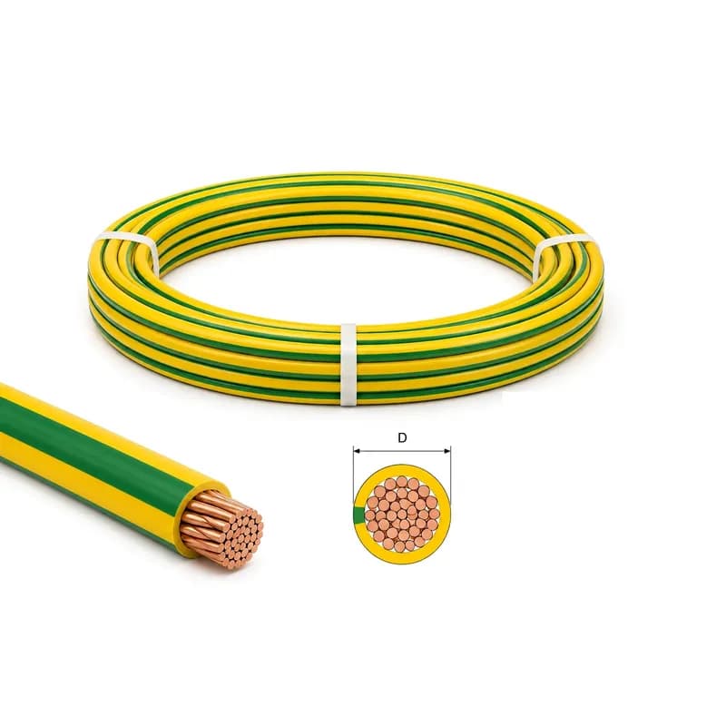
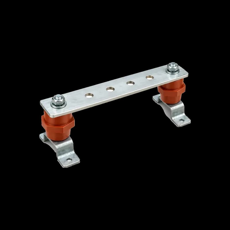
If a defect is found, the remedy may involve an earth bar with disconnect link, green and yellow earth cable, earthing and bonding clamps or, at designed locations, exothermic welded joints. Any connection should be chosen or replaced according to the conductor materials, environmental conditions and project design; simply buying a part is no substitute for testing after installation.
For a technical proposal: send the earthing/bonding drawing, a list of panels and equipment, the project location, operating status and the purpose of the test (initial handover, fault-finding or periodic inspection) to KALOT Group so the scope and measurement method can be defined.