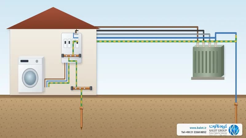
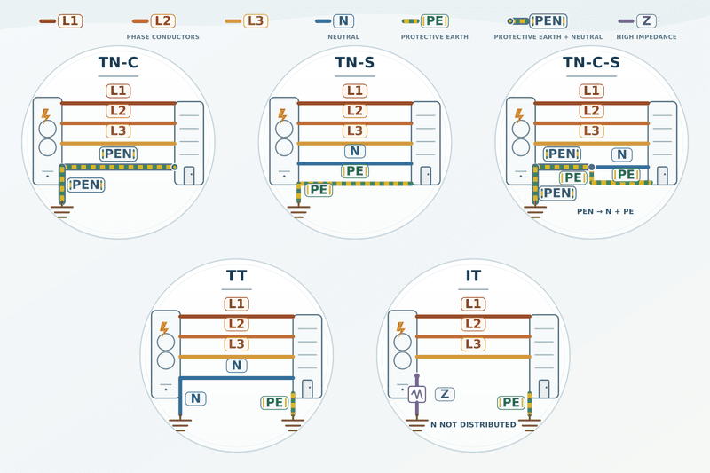
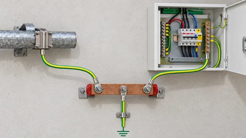
Earthing comes in two main forms: "protective earth" and "electrical earth". In specialist applications, concepts such as "functional earth" and "clean earth" also fall within this classification. Each of these systems is defined in standards such as IEEE 142, IEC 60364 and ANSI/NFPA 70, and has its own characteristics and uses. In this article, we review these systems side by side and answer three common questions about separating them.
Types of earthing system
1. Protective earth
- Target resistance: usually taken as below 2 ohms in design; the exact value is set by the protection method and the automatic disconnection of supply condition under IEC 60364-4-41.
- Use: protecting people's lives and equipment.
- Standards: IEC 60364-4-41 (protection against electric shock), IEEE 142 (recommendations for industrial earthing systems) and NFPA 70 (electrical safety requirements).
2. Functional earth
- Target resistance: usually below 1 ohm.
- Use: precision measuring and control equipment.
- Characteristics: low noise (below 1V), a path separate from other earthing systems and the use of shielded conductors.
3. Clean earth
- Target resistance: usually below 0.5 ohm.
- Use: telecommunication equipment, sensitive computer systems and data centres.
- Special requirements: a fully separate path, noise below 100mV and the use of special electrodes.
Comparing the standards
- IEC 60364: focuses on building power distribution systems.
- IEEE 142 (Green Book): a comprehensive guide to earthing systems in industry.
- ANSI/NFPA 70: safety and protection requirements.
- BS 7430: the British standard for earthing systems.
Safety and technical challenges of separating earthing systems
1. Is separating earth terminals sound and in line with safety standards?
Despite the bonding requirement, a clean earth can be created in these two ways:
Method one: galvanic isolation
- Using an isolating transformer
- Creating a separate earth reference
- Keeping the noise return path controlled
Method two: controlled bonding
- Single point connection
- Using EMI/RFI filters
- Shielded cables and separate routing
Standards and solutions:
- IEEE 1100: using a mesh network for bonding
- IEC 61000-5-2: methods for reducing electromagnetic interference
- ANSI/TIA-607: telecommunications bonding system
Important note: bonding must be made at one reference point to avoid creating current and noise loops.
2. Can two fully independent earthing systems be created? If so, why isn't this principle applied to all earthing systems?
Complete separation is not possible:
- Even with an isolating transformer, parasitic capacitances remain.
- At high frequencies, EMI/RFI effects are unavoidable.
- The actual earth is always a shared path.
Risks of separation:
- Possible dangerous potential differences
- Creating unwanted current paths
- Greater lightning and overvoltage risk
The right solution:
- Controlled bonding at one reference point
- Proper cable routing
- Using shields and filters
- Designing an earth mesh
3. Is there equipment or a method that can separate two earthing systems completely and effectively?
No equipment or method can make two earthing systems fully independent, and safety advises against trying. The right way is controlled bonding and equipotential bonding.