
Move your pointer over the image to zoom in
Complete Product Overview
Green and yellow earth cable (insulated copper earth wire) for protective conductors and bonding
Order Code: GYCC 006–300
Last updated:
Green and yellow earth cable from KALOT Group is a stranded copper conductor with green and yellow PVC insulation. It is used above ground as the earthing conductor from the earth pit bar to the main earth bar, the protective conductor (PE) of panels and circuits, and the bonding conductor for pipes, metal structures and equipment. We supply this cable in sizes from 6 to 300 mm², at a rated voltage of 450/750 V. The green and yellow colour makes the protective conductor identifiable along the whole route, on the earth bar and inside the panel, and its insulation separates the conductor from corrosion and from contact with dissimilar metals. Where mechanical damage is likely, run the cable in conduit or trunking.
We make the connections of green and yellow earth cable with tinned copper cable lugs on the earth bar, the earth pit bar and KALOT bonding parts. In soil and inside the earth pit up to the pit bar, we use bare copper conductor and pour concrete around the pit. The green and yellow cable starts at the pit bar, runs in a non-metallic, sunlight-resistant conduit from the pit to the building entry, and reaches the main earth bar inside the building either exposed or in conduit.
An identifiable protective conductor, from earth pit to panel
To choose green and yellow earth cable, weigh three things: the cable's role (earthing conductor, circuit protective conductor, main or supplementary bonding, lightning protection bonding), the fault current it must withstand, and where it will run (inside a building, on a wall, in conduit, inside a panel or outdoors). Green and yellow cable is used above ground. In soil and inside the earth pit, bare copper conductor takes its place.
- Class 2 stranded copper conductor with green and yellow PVC insulation, sizes 6 to 300
- Earthing conductor, protective conductor (PE) and bonding, above ground
- KALOT cable lugs, earth bars, pit bars and bonding parts for the connections
- Supplied in coils or on drums, cut to order; special sheaths made to order
From the pit bar upwards, never in soil
Green and yellow cable is not an electrode: its PVC insulation cuts off contact with the soil, so it plays no part in lowering earth resistance. In soil and inside the earth pit up to the pit bar, we use bare copper conductor. The green and yellow cable starts at the pit bar, runs in a non-metallic, sunlight-resistant conduit from the pit to the building entry, and reaches the main earth bar inside the building either exposed or in conduit. Topic 13 requires the earthing conductor, all the way to the main earth bar, to be visible or inside a protective non-metallic conduit.
Size follows the cable's role
Under IEC 60364-5-54 and Topic 13, if the protective conductor size is not calculated, it is taken as the same as the phase conductor up to 16, size 16 with phase conductors of 25 and 35, and half the phase size with larger ones. The main bonding conductor is at least 6 mm² and need not exceed 25. The "Selecting the earth cable size" table on this page shows the size for each role.
Green and yellow, for the protective conductor only
Under IEC 60445 the green and yellow combination is reserved for the protective conductor, and under IEC 60227-1 each colour covers 30 to 70 percent of the surface in every 15 mm of cable length. Do not use green and yellow cable for phase or neutral. The only exception is the PEN conductor, which is identified with a blue marking at both ends.
Class 2 stranded, not fine flexible
Our earth cable conductor is Class 2 stranded: it holds its shape on walls and earth bars and crimps into a standard cable lug. Fine flexible wire (Class 5) has very thin strands and is used for moving parts and tight wiring inside panels.
Drawings and datasheet
Green and yellow earth cable datasheet (PDF)You will find the cable cross-section and code table, the schematic from earth pit to main earth bar, the connection modes and the installation steps as PDF files alongside the datasheet.
Technical Product Information
Click to view enlarged
Feature | Value |
|---|---|
Product type | Single-core unsheathed cable with green and yellow PVC insulation, for protective conductors, bonding and earthing conductors |
Conductor | Annealed copper, stranded (multi-wire) Class 2 to IEC 60228 |
Insulation | Green and yellow PVC, conductor operating temperature up to 70 degrees Celsius |
Sunlight resistance | UV-protected insulation; in sunlight, run it in conduit |
Rated voltage | 450/750 V |
Reference standard | IEC 60227-3 (the 60227 IEC 01 family) |
Size (cross-section) | 6 to 300 mm² |
Outer diameter | From 4.7 mm (size 6) to 27.5 mm (size 300); size 50: 11.7 mm |
Weight per metre | From 0.07 kg (size 6) to 2.93 kg (size 300); size 50: 0.49 kg |
Special sheaths | Termite-resistant, rodent-resistant, low-smoke, high-temperature and oil-resistant PVC, made to order |
Supply form | Coils for short lengths and drums for long lengths; cut to order |
Order code | GYCC 006–300 |
Connections | Tinned copper cable lugs, earth bars, earth pit bars and KALOT bonding parts |
Main application | Earthing conductor from the pit bar to the main earth bar, protective conductor (PE), main and supplementary bonding, bonding of the lightning protection system |
Codes, sizes and specifications of green and yellow earth cable
Order code | Cross-section (mm²) | Outer diameter (mm) | Maximum resistance at 20 degrees (Ω/km) | Weight per metre (kg) |
|---|---|---|---|---|
GYCC 006 | 6 | 4.7 | 3.08 | 0.07 |
GYCC 010 | 10 | 6.1 | 1.83 | 0.11 |
GYCC 016 | 16 | 7.1 | 1.15 | 0.17 |
GYCC 025 | 25 | 8.8 | 0.727 | 0.27 |
GYCC 035 | 35 | 10.0 | 0.524 | 0.36 |
GYCC 050 | 50 | 11.7 | 0.387 | 0.49 |
GYCC 070 | 70 | 13.7 | 0.268 | 0.71 |
GYCC 095 | 95 | 15.8 | 0.193 | 0.96 |
GYCC 120 | 120 | 17.4 | 0.153 | 1.20 |
GYCC 150 | 150 | 19.4 | 0.124 | 1.48 |
GYCC 185 | 185 | 21.6 | 0.0991 | 1.79 |
GYCC 240 | 240 | 24.7 | 0.0754 | 2.34 |
GYCC 300 | 300 | 27.5 | 0.0601 | 2.93 |
"Size" is the conductor's nominal cross-section in mm². The maximum resistance of each size is the limit IEC 60228 allows for a Class 2 stranded copper conductor. We supply green and yellow earth cable in coils or on drums, cut to order. Our products are constantly improving and some dimensions may be updated, so please ask our specialists for the final dimensions before you buy.
Cable cross-section, cable end and code table
Download the cross-section, cable end and code table (PDF)
Earth cable construction: stranded copper conductor and PVC insulation
The conductor of green and yellow earth cable is made of annealed copper strands wound in concentric layers around a central strand. It is a Class 2 stranded conductor: it holds its shape on walls and earth bars and crimps correctly into a standard cable lug. Around the conductor is green and yellow PVC insulation, with a rated voltage of 450/750 V and a conductor operating temperature of up to 70 degrees. We supply the cable in coils for short lengths and on drums for long lengths, cut to order. Special termite-resistant, rodent-resistant, low-smoke, high-temperature and oil-resistant sheaths are also made to order.
Click to view enlarged
Applications of green and yellow earth cable
- Earthing conductor: from the earth pit bar to the earth bar or the building's main earth bar, in a non-metallic, sunlight-resistant conduit from the pit to the building entry, and exposed or in conduit inside the building. Below the pit bar, bare copper conductor is used.
- Protective conductor (PE): the protective conductor of main and sub-panels, motor and pump circuits and equipment, up to the panel's PE bar. For background, see the difference between protective earth (PE) and functional earth (FE) and the TN-S system.
- Main bonding: connecting metal water and gas pipes, the steel frame, service ducts and foundation earthing bonding points to the main earth bar.
- Supplementary bonding: bonding equipment, cable trays and ladders, steel tanks with the steel bonding cylinder, and raised floor pedestals with the pedestal clamp. See bonding and equipotential bonding.
- Lightning protection bonding: connecting bonding bars to the earthing system, and metal installations inside the building to the bonding bar. IEC 62305-3 requires 16 and 6 mm² of copper for these two, respectively.
- Metal structures, towers and cable trays: with a tinned cable lug or TECD clamps and TECS (sizes 16 to 185) and PTEC (120 to 300), stripping the cable to the length of the clamp. On galvanised structures, only in air and above ground level, with the joint covered by an anti-corrosion coating and no copper above the galvanised parts.
- Foundation earthing and columns: connecting the reinforcing bar bonding plate and the bonding point to the main earth bar. The bonding design and installation guideline calls for a non-flexible copper conductor of at least 16 mm² beside the columns between floors, and makes insulation mandatory for columns that will be plastered.
- Solar power plants: bonding panel frames and the supporting structure. Run the bonding cable parallel and close to the DC and AC cables, inside a sunlight-resistant conduit or channel. On aluminium or galvanised structures, use a tinned cable lug, cover the joint with an anti-corrosion coating, and do not place copper above galvanised parts. See lightning protection of photovoltaic systems.
From earth pit to main earth bar: where bare conductor goes and where green and yellow cable goes
Download the schematic from earth pit to main earth bar (PDF)
Earth cable connection modes with KALOT cable lugs, earth bars and bonding parts
Download connection modes (PDF)
Installation steps for green and yellow earth cable
- Set the cable size according to its role, from the "Selecting the earth cable size" table on this page or by calculating the fault current.
- Run the earthing conductor from the pit bar in a non-metallic conduit to above ground level, then exposed or in conduit to the main earth bar (Topic 13). Outside the building and on roofs, run the cable in a sunlight-resistant conduit: our cable's insulation is UV-protected, but long exposure to the sun damages it, and Topic 13 also requires cables to be protected from direct sunlight.
- Do not unroll, bend or install the cable in air colder than 3 degrees Celsius, unless the cable has been kept at 20 degrees or more for at least 72 hours beforehand and the work is finished within 8 hours (Topic 13).
- Keep the bending radius at no less than 8 times the sum of the cable's outer diameter (D) and the conductor diameter (d, over the strands) (Topic 13). For size 50 (D of 11.7 mm and d of 8.9 mm), that is at least 165 mm.
- Fix sizes 35 to 95 on walls with the insulated one-hole clip (ICG) and other sizes with an insulated clip matching the cable, without cutting or crushing the insulation. Topic 13 sets the clip spacing on horizontal runs at no more than 20 times the cable's outer diameter (234 mm for size 50) and accepts up to 50 percent more on vertical runs.
- Strip the insulation at the cable end to the depth of the lug barrel, without cutting or spreading the strands.
- Crimp a copper cable lug of the cable's size with a hydraulic press and matching die, and fit a green and yellow heat-shrink sleeve over the barrel. Topic 13 does not allow a lug connected by solder alone.
- Fix the lug with a bolt, washer and nut to the earth bar or pit bar, with each conductor in its own hole. On the main earth bar, each conductor must be separate and removable only with a tool (IEC 60364-5-54). Tighten the nuts according to the manufacturer's instructions.
- Inside the earth pit, use bare copper conductor below the pit bar and take the green and yellow cable upwards from the pit bar. Pour concrete around the earth pit.
- At the connection point of the earthing conductor and bonding conductors, fit a permanent label reading "Safety electrical connection: do not remove".
- After installation, measure the continuity of every protective and bonding conductor with a milliohmmeter (IEC 60364-6) and record the result with the date in the earthing system file.
Download the installation steps (PDF)
Installation tools
Cable stripping tool, cable cutter, hydraulic lug press with matching die, green and yellow heat-shrink sleeve and hot air blower, spanner for the bar bolts and nuts, tape measure, permanent labels and a continuity tester (milliohmmeter).
Continuity checks and periodic inspection
At each inspection, check the following: the continuity of every protective and bonding conductor with a milliohmmeter; the condition of the insulation (cracking, hardening and fading under sunlight, cuts near clips and edges); the tightness of the cable lugs and the absence of green corrosion on their barrels; and that the labels are in place on the main earth bar. To measure earth resistance, use a tool to separate the earthing conductor at the disconnect link on the main earth bar. Before separating it, switch off the installation's power or use the clamp-on method, which needs no disconnection. Do not do this in stormy weather, and close the link straight away after measuring. Topic 13 requires this facility for periodic measurement and also calls for periodic inspection of the pit, the earthing conductor and the connections. For the method, see how earth termination resistance is measured.
Selecting and requesting a price for green and yellow earth cable
To request a price for green and yellow earth cable, send our specialists the size (cross-section), length and supply form (coil or drum), any special sheath you need (termite-resistant, rodent-resistant, low-smoke, high-temperature or oil-resistant), the application (earthing conductor, panel protective conductor or bonding) and the accessories you need (cable lugs, earth bars, disconnect links, insulated clips, bonding plates and bare copper conductor for soil and pit). If you also send the project's earthing drawing or panel single-line diagrams, our specialists at KALOT Group will give you the list of cable and accessories along with current prices.
Click to view enlarged
The green and yellow colour makes the protective conductor identifiable along the whole route, on the earth bar and inside the panel. Topic 13 requires all conductors, including the protective conductor, to be identifiable by insulation colour along the whole cable length. The PVC insulation separates the conductor from corrosion and from contact with dissimilar metals (IEC 60364-5-54 counts only conduit, trunking or similar covers as mechanical protection). Topic 13 requires a protective conductor running with the circuit in conduit and ducts to be insulated, and also uses insulated conductors on cable trays and ladders for corrosion protection and identification. IEC 62305-3 considers a PVC-sheathed copper bonding conductor passing through a concrete wall safe from corrosion. Keep two points in mind as well: green and yellow cable is not an electrode and does not replace bare conductor in soil; and its 450/750 V insulation is not rated for lightning impulse voltage. IEC 62305-3 requires an insulated down conductor to withstand a 100 kV 1.2/50 impulse (for example, at least 3 mm of cross-linked polyethylene), so do not treat this cable as a substitute for the separation distance or for an insulated down conductor.
Advantages of KALOT green and yellow earth cable
- Easy identification: the green and yellow colour shows the protective conductor along the whole route, on the earth bar and inside the panel.
- Class 2 stranded conductor: holds its shape on walls and earth bars and crimps into a standard cable lug.
- From 6 to 300: a complete family, from supplementary bonding to the protective conductors of large panels and substations.
- 450/750 V insulation: separates the conductor from corrosion and from contact with dissimilar metals; against impact, conduit or trunking is needed.
- Special sheaths to order: termite-resistant, rodent-resistant, low-smoke, high-temperature and oil-resistant PVC.
- Connections with KALOT products: cable lugs, earth bars, earth pit bars, reinforcing bar bonding plates and metal structure clamps, all from one supplier.
Selecting the earth cable size by its role
Cable role | Minimum size in the standards (mm²) | Reference | Our recommendation |
|---|---|---|---|
Circuit protective conductor, with phase conductor up to 16 | Same size as the phase conductor | IEC 60364-5-54; Topic 13 | GYCC of the same size as the phase conductor (from size 6) |
Circuit protective conductor, with phase conductor of 25 and 35 | 16 | IEC 60364-5-54; Topic 13 | GYCC 016 |
Circuit protective conductor, with phase conductor larger than 35 | Half the phase conductor size | IEC 60364-5-54; Topic 13 | Next standard size up; for phase conductor 95, GYCC 050 |
Protective conductor separate from the circuit cable | 2.5 with mechanical protection and 4 without it | IEC 60364-5-54; Topic 13 | GYCC 006 and above |
Protective conductor of equipment with leakage current above 10 mA | 10 | IEC 60364-5-54 | GYCC 010 and above |
Earthing conductor, from the pit bar to the main earth bar | 6, and no less than the size needed for the fault current; 16 with a lightning protection system; Topic 13 recommends the electrode table size | IEC 60364-5-54; IEC 62305-3 (Table 8); Topic 13 | Same size as the bare conductor inside the pit; at least GYCC 025 |
Main bonding to the main earth bar | Half the largest protective conductor; at least 6; need not exceed 25 | IEC 60364-5-54; Topic 13 | GYCC 006 to GYCC 025 |
Supplementary bonding | 2.5 with mechanical protection and 4 without it; 4 in bathrooms; equipment to equipment: the smallest protective conductor; equipment to pipe: half the protective conductor | IEC 60364-5-54; Topic 13; supplementary bonding guideline | GYCC 006 and above, based on the equipment's protective conductors |
Lightning protection bonding: bonding bar to the earthing system | 16 | IEC 62305-3 | GYCC 016 and above |
Lightning protection bonding: metal installations inside the building to the bonding bar | 6 | IEC 62305-3 | GYCC 006 and above |
Bonding conductor beside columns that will be plastered | 16, insulated | Bonding design and installation guideline | GYCC 016 |
The sizes come from IEC 60364-5-54:2011, Topic 13 of the Iranian National Building Regulations (1395 edition), IEC 62305-3:2010 and the bonding guidelines of the Construction Engineering Organisation. The design and the fault current calculation set the final size: S = I√t / k, with k of 143 for green and yellow cable run separately and not bundled with other cables, and 115 for cable in a bundle, conduit or trunking with other cables or wires. For background on the protective conductor, see the difference between protective earth (PE) and functional earth (FE).
See these products too
Product | When |
|---|---|
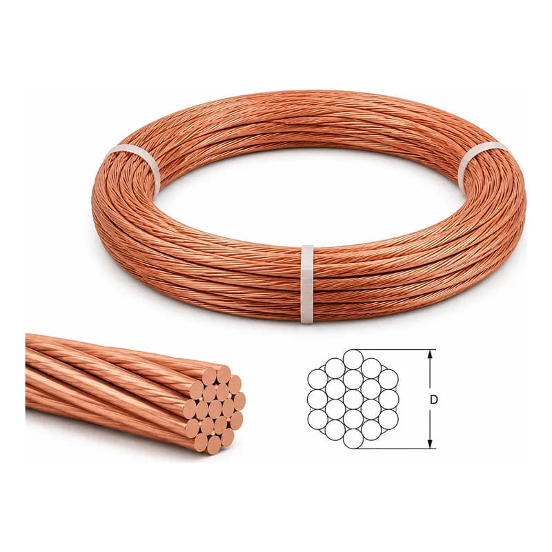
Uninsulated conductor for soil, the earth pit up to the pit bar, concrete, down conductors and the roof network. | |
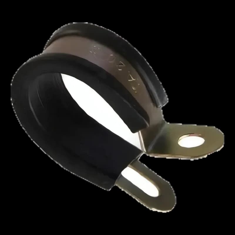
Fixes green and yellow cable of sizes 35 to 95 on walls. | |
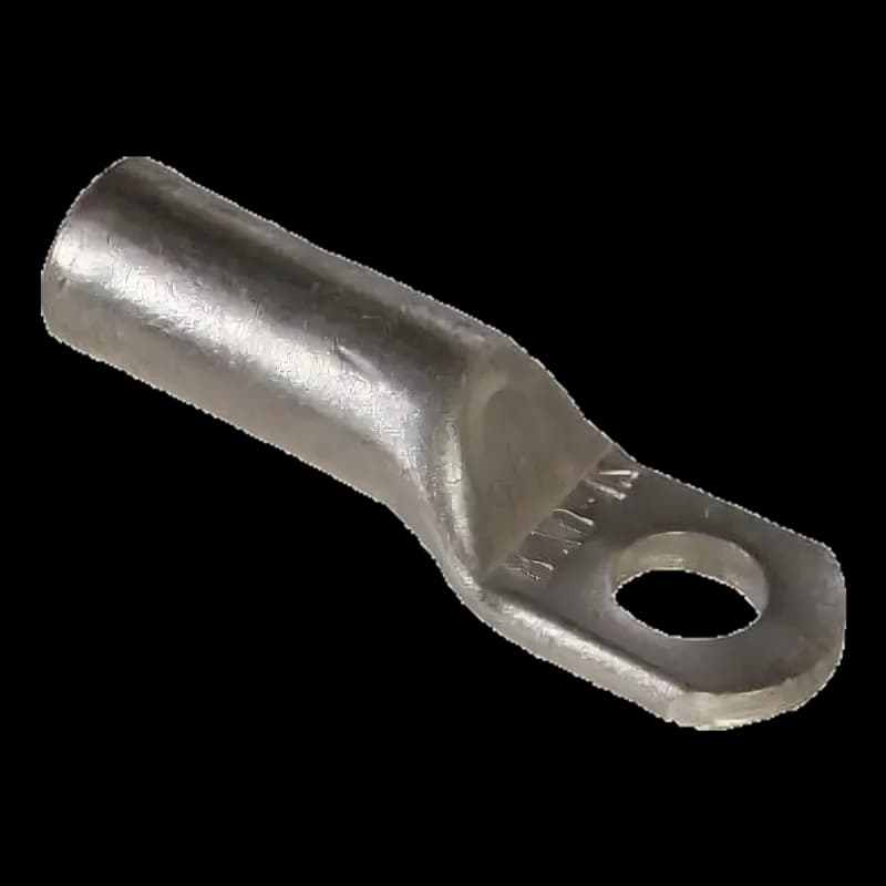
Tinned copper cable lug for sizes 6 to 300. | |
Two-bolt tinned copper cable lug for sizes 6 to 300. | |
Main earth bar with a link that separates the earthing conductor for measurement. | |
For two earthing conductors or two earthing systems. | |
Separates the earthing conductor and opens only with a tool. | |
Connection point for the bare conductor and the green and yellow cable inside the pit. | |
For an inspectable connection on the top of the earth rod; concrete is poured around it. | |
Foundation earthing connection point with a green and yellow cable tail. | |
Foundation earthing connection point on a concrete wall or column. | |
Reinforcing bar connection point with an M10 bolt for the cable lug. | |
Cable lug connection point on tanks and steel structures. | |
Two-piece clamp for connecting conductor to metal structures (TECD) | Connects the conductor to plates, structures and towers, in air. |
Bonds the raised floor pedestals of server and panel rooms. | |
Bonding for doors, gates and moving parts. |
Compare all earthing and bonding clamps in the "Which clamp should we choose?" table.
IEC 60227-3 (single-core unsheathed PVC-insulated cables for fixed wiring, up to 450/750 V) defines this family under the type name 60227 IEC 01, and IEC 60227-1 sets its general requirements: PVC insulation for fixed installation and a conductor operating temperature of up to 70 degrees. IEC 60228 sets the minimum number of strands and the maximum resistance of each size. Our green and yellow earth cable belongs to this family: rated voltage 450/750 V and a Class 2 stranded conductor.
IEC 60445 reserves the green and yellow combination for identifying the protective conductor, and IEC 60227-1 states that in every 15 mm of cable length, one of the two colours covers at least 30 and no more than 70 percent of the surface. An insulated green and yellow PEN conductor is identified with a blue marking at both ends. Topic 13 requires all phase, neutral and protective conductors to be identifiable by insulation colour at the terminals and along the whole cable length, and marks the panel's protective conductor bar with PE.
IEC 60364-5-54:2011 (earthing arrangements and protective conductors) requires the protective conductor to be the same size as the phase conductor up to 16, size 16 with phase conductors of 25 and 35, and half the phase size with larger ones, or calculates it with S = I√t / k. For a copper conductor with seventy-degree PVC insulation, k is 143 when it runs separately and is not bundled with other cables, and 115 when it is in a bundle, conduit or trunking with other cables or wires. It requires a protective conductor separate from the circuit cable to be at least 2.5 mm² with mechanical protection and 4 mm² without it, and an earthing conductor to be at least 6 mm² and large enough for the fault current, and a note recommends 16 mm² with a lightning protection system. It requires a main bonding conductor of at least 6 mm² and does not consider more than 25 mm² necessary. Each conductor on the main earth bar must be separate and removable only with a tool, and a connection that relies on solder alone is not accepted.
Topic 13 of the Iranian National Building Regulations (1395 edition) gives the same sizes for the protective conductor and for main and supplementary bonding. It requires supplementary bonding in bathrooms to be at least 4 mm² and treats the main earth bar as copper of at least 50 mm². It requires the earthing conductor, from the electrode connection to the main earth bar, to be visible or inside a protective non-metallic conduit, and counts the part in contact with soil or concrete as part of the electrode. It requires a protective conductor running with the circuit in conduit and ducts to be insulated, and cables to be protected from direct sunlight. It sets the bending radius of a non-metallic sheathed cable at no less than 8 times the sum of the outer diameter and the conductor diameter. It does not allow installation in air colder than 3 degrees unless the cable is warmed beforehand, and it forbids a cable lug connected by solder alone.
IEC 62305-3:2010 (protection of structures against lightning) sets the minimum copper cross-section at 16 mm² for bonding conductors between bonding bars and the earthing system, and 6 mm² for bonding metal installations inside the building to the bonding bar. The same standard does not count a thin coating (such as half-millimetre PVC) as insulation and, to insulate a down conductor against touch voltage, requires it to withstand a 100 kV impulse. The insulation of a 450/750 V cable is not rated for such an impulse and does not replace the separation distance. It considers a PVC-sheathed copper bonding conductor passing through a concrete wall safe from corrosion.
The bonding guidelines of the Construction Engineering Organisation make an insulated copper conductor of at least 16 mm² mandatory beside columns that will be plastered, to prevent corrosion, and require the PVC insulation of a rooftop bonding conductor to be protected from the sun's ultraviolet rays. They also do not accept a cable tray in place of a supplementary bonding conductor.
BS 7671 (the UK wiring regulations) accepts single-core unsheathed cable only inside conduit, duct or trunking, except when it is a protective conductor, and treats fully green and yellow cable as a protective conductor only. The same regulations require a permanent label reading "Safety electrical connection: do not remove" where the earthing conductor connects to the electrode and at bonding conductors. BS 7430 also notes that a conductor's insulation limits its maximum permissible temperature under fault current.
Green/yellow earth cable: section and use
Documents & Downloads
Catalogues & datasheets
Drawings & schematics
- Green and yellow earth cable cross-section, cable end and code tableLanguage: Persian (opens in a new tab)
- Earth pit to main earth bar schematic with green and yellow earth cableLanguage: Persian (opens in a new tab)
- Green and yellow earth cable connection modesLanguage: Persian (opens in a new tab)
- Green and yellow earth cable installation stepsLanguage: Persian (opens in a new tab)
Frequently Asked Questions
What is green and yellow earth cable, and how does it differ from bare copper conductor?
Green and yellow earth cable (known in the market as green and yellow earth wire or insulated earth wire) is a stranded copper conductor with green and yellow PVC insulation. It is used above ground as the earthing conductor (from the earth pit bar to the main earth bar), the protective conductor (PE) and the bonding conductor. Bare copper conductor has no insulation and is used in soil, inside the earth pit up to the pit bar, in concrete, and for down conductors and the roof network.
Can green and yellow earth cable be placed in soil, in an earth pit or inside an earth inspection pit?
We do not do this. Green and yellow cable is not an electrode: its PVC insulation cuts off contact with the soil, so it plays no part in lowering earth resistance, and as an unsheathed cable it is not built for burial in soil either. In soil and inside the earth pit up to the pit bar we use bare copper conductor. The green and yellow cable starts at the pit bar, runs in a non-metallic, sunlight-resistant conduit from the pit to the building entry, and reaches the main earth bar inside the building either exposed or in conduit. Topic 13 of the Iranian National Building Regulations requires the earthing conductor to be visible or inside a protective non-metallic conduit.
What size should the earth wire of an electrical panel be?
Under IEC 60364-5-54 and Topic 13, the protective conductor is the same size as the phase conductor up to 16 mm², size 16 with phase conductors of 25 and 35, and half the phase size with larger phase conductors (if that is not a standard figure, the next standard size up). For equipment with a leakage current above 10 mA, it is at least 10 mm². The designer can also calculate the size with S = I√t / k.
What size should the earth cable be from the earth pit to the main earth bar: 16, 25 or 50?
IEC 60364-5-54 asks for an earthing conductor of at least 6 mm² and sizes it for fault current in the same way as a protective conductor. When a lightning protection system is connected to the electrode, IEC 62305-3 requires at least 16 mm² of copper between the bonding bar and the earthing system. Topic 13 recommends that the earthing conductor match the electrode table, that is 25 mm² stranded copper. We choose this cable in the same size as the bare copper conductor inside the pit (for example, both at 50 mm²) and do not recommend less than 25 mm². The design sets the final size.
Which is better, flexible or rigid earth wire? Which type is KALOT's earth cable?
Our earth cable has a Class 2 stranded conductor to IEC 60228, sometimes called "rigid" wire in the market. It holds its shape on walls and earth bars and crimps into a standard cable lug. Fine flexible wire (Class 5) has very thin strands, is used for moving parts and tight wiring inside panels, and needs its own lugs and ferrules. For doors and gates, see our flexible copper bonding tape.
What are the outer diameter and weight per metre of size 50 green and yellow earth cable?
Our GYCC 050 cable has an outer diameter of 11.7 mm and weighs 0.49 kg per metre. The outer diameter, maximum resistance and weight of every size, from 6 to 300, are in the code table on this page.
How do we connect earth cable to the earth bar and the earth pit bar?
Strip the cable end to the length of the lug barrel, crimp a matching copper cable lug with a hydraulic press and matching die, fit a green and yellow heat-shrink sleeve, and fix the lug with a bolt, washer and nut to the earth bar or earth pit bar, with each conductor in its own hole. Inside the pit, the connection to the earth rod is made with bare copper conductor and a brass clamp, and the green and yellow cable starts at the pit bar.
How do we connect green and yellow earth cable to a building's steel frame, a tower, a cable tray or a metal structure?
Use a tinned cable lug on the structure, or TECD clamps and TECS (sizes 16 to 185) and PTEC (120 to 300), stripping the cable to the length of the clamp. On tanks and steel structures, the steel bonding cylinder provides the fixing point for the lug. On galvanised structures, towers or cable trays, make the joint only in air and above ground level, cover it with an anti-corrosion coating, and do not place copper above galvanised parts. Do not use a cable tray in place of a bonding conductor: connect it to the earth bar with a bonding conductor.
What does green and yellow on an earth wire mean, and can it be used for phase or neutral?
No. Under IEC 60445 the green and yellow combination is reserved for the protective conductor, and under IEC 60227-1 each colour covers 30 to 70 percent of the surface in every 15 mm of cable length. Do not use green and yellow cable for phase or neutral, and do not re-mark it with another colour. The only exception is the PEN conductor, which is identified with a blue marking at both ends.
What fault current can green and yellow earth cable withstand?
IEC 60364-5-54 calculates the required cross-section with S = I√t / k. For copper with seventy-degree PVC insulation run separately, k is 143, so a 50 mm² cable withstands 50 × 143, that is 7150 A, for one second. If the cable is in a bundle, conduit or trunking with other cables or wires, k is 115 and the same cable withstands 5750 A. These figures are standard calculations, and the designer chooses the final size from the project's fault current and disconnection time.
Is green and yellow earth cable suitable as a lightning protection down conductor?
For down conductors and the roof network, we recommend bare copper conductor or copper tape. Green and yellow is reserved for the protective conductor. IEC 62305-3 does not count thin PVC coating as insulation and requires an insulated down conductor to withstand a 100 kV impulse, and 450/750 V insulation is not rated for such an impulse. Use green and yellow cable for bonding installations to the lightning protection system.
How do we run green and yellow earth cable outdoors and on roofs?
The insulation of our green and yellow earth cable is UV-protected and has some resistance to sunlight, but long exposure to the sun damages it. Topic 13 also requires cables to be protected from direct sunlight, and the supplementary bonding guideline requires the PVC insulation of a rooftop bonding conductor to be UV-protected. So outdoors, run the cable inside a sunlight-resistant conduit. Do not unroll or install the cable in air colder than 3 degrees, and do not place it inside a gutter or rainwater pipe: because of moisture corrosion, IEC 62305-3 does not accept even an insulated conductor inside a gutter.
What is the bending radius of earth cable, and how is it fixed to a wall?
Topic 13 sets the bending radius of a non-metallic sheathed cable at no less than 8 times the sum of the cable's outer diameter and the conductor diameter. For size 50 (outer diameter 11.7 mm, conductor diameter 8.9 mm), that is at least 165 mm. On walls, fix sizes 35 to 95 with the insulated one-hole clip (ICG) and other sizes with an insulated clip matching the cable, without cutting the insulation. Topic 13 sets the clip spacing on horizontal runs at no more than 20 times the cable's outer diameter.
How is the price of green and yellow earth cable set, and what should we send for a quote?
The price depends on the size, length, supply form (coil or drum), any special sheath and the current price of copper. Send our specialists the size, length, application (earthing conductor, panel protective conductor or bonding) and the cable lugs and earth bars you need, and they will quote the current price along with a list of accessories.
Have a Technical Question?
KALOT Group's technical experts are ready to answer your questions about lightning rods and earthing systems.