
Move your pointer over the image to zoom in
Complete Product Overview
Two-way conductor-to-conductor clamp
Order Code: TC35 · TC57 · TC95
Last updated:
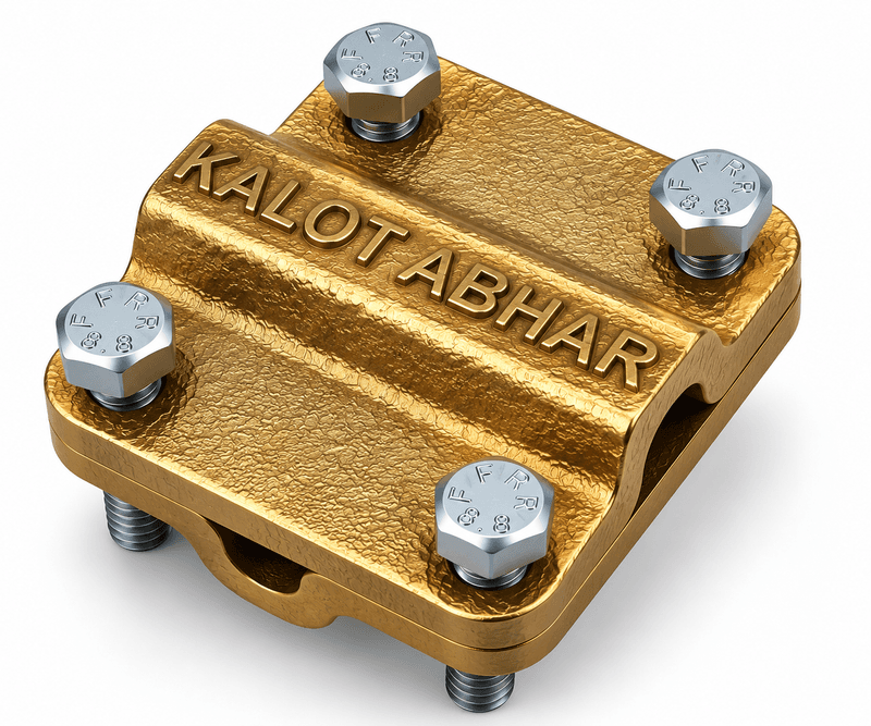
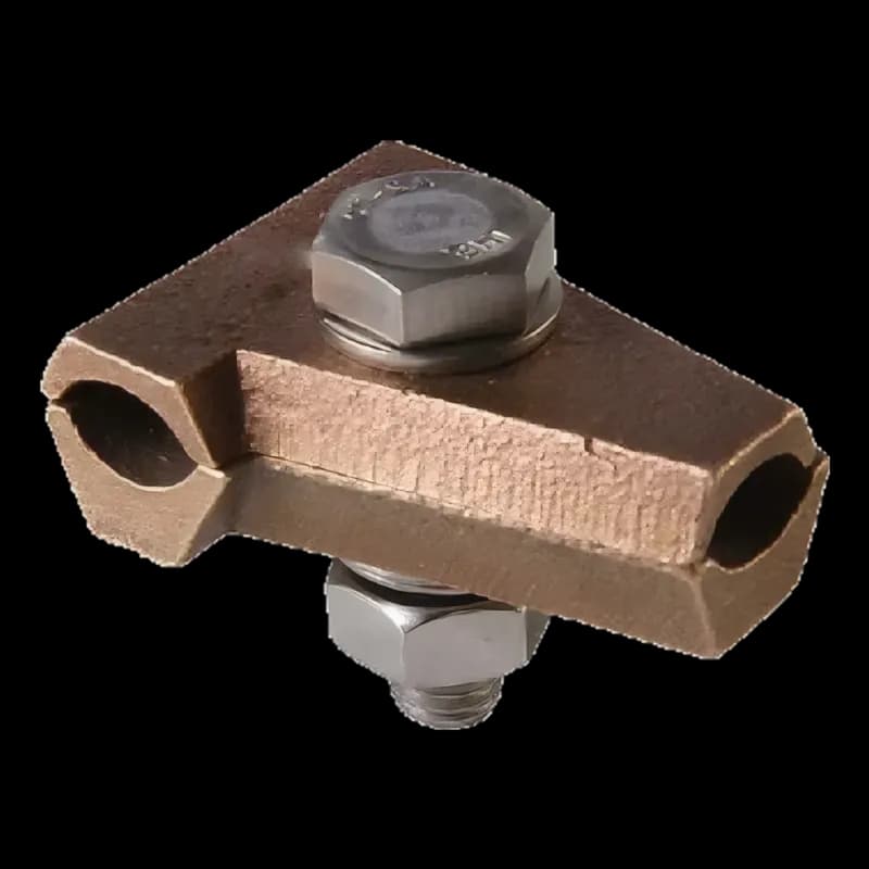
The KALOT two-way conductor-to-conductor clamp (test clamp, models TC35, TC57 and TC95) joins the ends of two round copper conductors. Its two-piece brass body has a diagonal channel under a raised section, where the two conductor ends sit, and two stainless steel bolts at opposite corners close the pieces over the conductors. In a lightning protection system it is usually installed between the down conductor and the earth conductor, so that opening the bolts separates the two when the earthing system is measured. All three models share the same dimensions, and the model is chosen by conductor cross-section.
We manufacture this clamp for a testable connection between the down conductor and the earth conductor in your projects.
Joins the ends of two round conductors
The ends of two round copper conductors sit in the diagonal channel under the raised part of the body and are held between the two clamp pieces.
A test point that opens
Opening the bolts separates the earth conductor from the down conductor, so the earthing system can be measured on its own, and the connection is then restored.
Brass body with two stainless steel bolts
The two-piece brass body closes with two stainless steel bolts at opposite corners. Dimensions are the same across all three models.
Technical Product Information
Feature | Value |
|---|---|
Section type | Two-way conductor-to-conductor clamp (test clamp, Test Clamp) |
Body material | Brass |
Bolts | Two stainless steel bolts, at opposite corners |
Structure | Two pieces; diagonal conductor channel under the raised part of the upper piece |
Conductor type | Round copper conductor |
Application | Joining the ends of two conductors; test point between down conductor and earth conductor |
Models and dimensions
Product code | Conductor cross-section (mm²) | L (mm) | W (mm) | H (mm) |
|---|---|---|---|---|
TC35 | 35 | 47 | 47 | 22 |
TC57 | 50 to 70 | 47 | 47 | 22 |
TC95 | 95 | 47 | 47 | 22 |
Click to view enlarged
The drawing shows top and side views of the clamp. L, W and H are marked on it, and their values for all three models are 47 × 47 × 22 mm. The drawing is schematic and is not a manufacturing drawing.
Click to view enlarged
The exploded view shows the two clamp body pieces opened out: the upper piece with its raised section over the diagonal channel, two stainless steel bolts at opposite corners, and the down conductor and earth conductor, which come in from opposite corners along the channel and sit on the lower piece.
L and W are 47 mm and H is 22 mm, the same for all three models TC35, TC57 and TC95.
Click to view enlarged
The mechanical and electrical role of the test clamp
On the route from the down conductor to the earthing system, this clamp does two jobs at once:
- Mechanical role: the ends of the down conductor and the earth conductor sit in the diagonal channel between the two body pieces, and two stainless steel bolts close the pieces over the conductors.
- Electrical role: this same connection provides electrical continuity between the down conductor and the earth conductor, so the clamp is part of the conductor route, not just a holder for it.
- Test point: opening the bolts separates the two conductors so the earthing system can be measured on its own. After measuring, the clamp is closed again and the conductors are checked for tightness.
As stated by KALOT Group, this clamp is designed for heavy duty use (Heavy Duty): besides holding the conductors mechanically, it must withstand any lightning current or network fault current that may pass through it, without the joint loosening or being damaged. That is why the brass alloy of the body and its dimensions were chosen to meet this need.
Application
This clamp joins the ends of two round copper conductors. In a lightning protection system, the down conductor usually enters the diagonal channel from one side and the earth conductor from the other. When the earthing system is measured, opening the bolts separates the two conductors, and the connection is restored after the test.
Installation sequence
- Choose the clamp model to match the conductor cross-section (TC35, TC57 or TC95).
- Place the two conductor ends from opposite sides into the diagonal channel of the upper piece.
- Fit the lower piece beneath it and tighten the two bolts evenly.
- After each measurement, close the joint again and check that the conductors are tight.
Test joint and down conductor test clamps
Documents & Downloads
Catalogues & datasheets
Drawings & schematics
- Dimensional drawing of the two-way conductor-to-conductor clamp (PDF)Language: Persian (opens in a new tab)
- Test clamp installation schematic | down conductor and earth conductor (PDF)Language: Persian (opens in a new tab)
- Exploded drawing of the two-way conductor-to-conductor clamp (PDF)Language: Persian (opens in a new tab)
Frequently Asked Questions
What is a two-way conductor-to-conductor clamp used for?
It joins the ends of two round copper conductors, and in a lightning protection system it is usually installed as a test point between the down conductor and the earth conductor.
Why is it called a test clamp?
Because opening the bolts separates the earth conductor from the down conductor, so the earthing system can be measured on its own.
Which model should I choose?
The model is chosen by conductor cross-section: TC35 for 35, TC57 for 50 to 70 and TC95 for 95 mm². Body dimensions are the same across all three models.
What are the clamp dimensions?
Length and width of 47 mm and height of 22 mm, for all three models.
Have a Technical Question?
KALOT Group's technical experts are ready to answer your questions about lightning rods and earthing systems.