In a ground-mounted solar plant, panel rows, DC cables, inverter stations and the monitoring system are spread over a wide area. Lightning can strike the structure or the protection system directly, or bring overvoltage to the equipment through induction and incoming lines. An effective design coordinates external protection, SPDs, bonding and earthing across the whole site.
Short answer: first assess the lightning risk and the need for an LPS. Then design the protected volume on the real geometry of the panels, inverters and cable routes; set the separation distance or deliberate bonding; select suitable SPDs on the PV-DC side, the AC side and data lines; and test the continuity of the protective connections and the earth network. One air terminal, even with a large calculated protection radius, does not replace these layers.
KALOT's experience in ground-mounted solar plants in Iran
Drawing on our project record, we at KALOT Group have equipped about 140 ground-mounted solar plant projects in Iran with earthing and direct lightning strike protection systems. ESE air terminal solutions, including the ACTIVE 1D+ family, are part of our equipment range; the final model and layout at each site must come from that project's own design.
On a new project, this experience does not mean one fixed recipe for every plant. Our technical team can review the drawing of rows and stations, cable routes, soil data and risk level, then propose the layout of terminals and down conductors, the earth network, bonding and surge protection points in one coordinated design. The deliverable should be a calculated drawing, equipment specifications and a test and maintenance programme.
Which parts of a solar plant does lightning damage?
In a ground-mounted plant, arrays sit in the open, DC cables run along the rows and transmission routes, inverters stand in separate stations and monitoring links sit elsewhere. This spread creates many paths for lightning effects and overvoltage to enter. IEC TR 63227 deals specifically with protecting PV power supply systems against lightning and surges of atmospheric origin.
Event | Path of effect | Likely consequence | Relevant protection layer |
|---|---|---|---|
Direct strike on a panel row, a station or the LPS | Lightning current in the air terminal, down conductor, structure and earth | Physical damage, side flash, touch hazard and fire | External protection, separation distance or bonding, and overvoltage protection |
Strike near the site | Voltage induced in DC, AC and data cable loops | Failure of the inverter, monitoring or modules | Sound routing, reduced loop area and coordinated SPDs |
Surge entering from the grid or communication lines | AC panel, data link or sensors | Disrupted or halted generation and damage to controls | SPDs at suitable AC and data boundaries |
A plant's rated power alone does not decide whether external protection is needed; for example, "above 10 kW" is not a general threshold for requiring an LPS. The decision comes from the risk assessment, the characteristics of the structure and site, local regulations and the consequence of a service outage.
From risk assessment to choosing a protection strategy
At the start of a project, we review the location, lightning flash density, the size and height of the structure, incoming lines, equipment value, the presence of people and the consequence of system outage. IEC 62305-2:2024 sets out the risk assessment method for a structure. If external protection is needed, the system type and protection level are set for designing the protected volume; its effect on panels and cables is then analysed.
In a ground-mounted plant, panel rows, inverter stations, combiner panels, the fence, cable routes, uneven terrain and points of personnel access all appear in the site model. The down conductor route and the earth termination system must not unintentionally carry lightning current through the panel structure or DC cables. If a project is on a roof, the building's existing LPS and its separation distance must also be reviewed separately; the examples in this guide focus on ground-mounted plants.
Two different topics: external protection steers a direct strike into a controlled path; surge protection limits transient overvoltage in power and data circuits. Having one does not remove the need to review the other.
How should external protection be laid out in a ground-mounted solar plant?
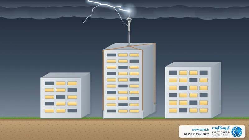
In an approach based on IEC 62305-3:2024, the protected volume of the air-termination system is designed with accepted methods such as the rolling sphere, the protection angle or the mesh. Panels and sensitive cables must sit in suitable positions relative to air terminals and down conductors. The height of an air rod alone does not show that every PV row is inside the protected volume.
On a PV farm, masts and conductors must be reviewed together for protected volume, shading on the rows, maintenance access and touch hazard. Shade from a mast or conductor can affect generation; how much depends on where the shadow falls, cell connections, bypass diodes, string layout and time of day. The designer must weigh the sun's path and the array's electrical performance alongside lightning protection.
If the separation distance between the LPS and the metal frames and PV circuits is maintained, direct lightning current entering the electrical paths can be limited to the designed extent. If this distance cannot be achieved in part of the site, the design must include a deliberate connection with adequate current capacity, a suitable SPD selection and control of the shared current path. Accidental contact of a down conductor with a rail, cable tray or frame is not a solution.
What advantage does an ESE air terminal offer a solar site?
An ESE, or early streamer emission air terminal, is an option for external protection on projects where the local standard and competent authority accept the method. The design reference for this method is the French NF C 17-102:2011; its protection radius comes from the model, the tested ΔT value, the effective height h above the highest protected point and the protection level. This radius is not a fixed figure printed on the device's box. The ESE method must not be presented as an IEC 62305 calculation method; the two references use different design methods.
On open sites with many rows, one well-positioned independent mast may reduce the number of terminals and bases compared with another layout. This can cut installation time, shading and part of the equipment cost; but the economic result only becomes clear after comparing drawings, the number of down conductors, the earth network, surge equipment, cabling, maintenance and acceptance under local regulations. No claim of "always cheaper" or "one device for every plant" follows from a nominal radius.
For plants that need several terminals and where purchase budget matters greatly, Franklin France ACTIVE 1D+ is the more economical of these two families for an initial enquiry. The family has four models, 12, 25, 45 and 60 microseconds, works from the storm's natural electric field and uses a dedicated tester for performance checks. The model should be chosen after calculating the protected volume; buying a cheaper model does not necessarily lower total project cost if it requires more masts or more conductor routes.
Franklin France ACTIVE 4D can be considered for projects where features such as storm detection, strike counting and remote testing and monitoring have value for the operator and the budget is available. For example, in the 60 microsecond models of these two families, the tabulated radii are equal at the same height and protection level; the choice should be weighed on monitoring features, test method, purchase and maintenance cost and the actual specifications of the sales offer. Neither replaces SPDs, bonding or earthing.
ACTIVE 1D+ model at h=5 m | Level I | Level II | Level III | Level IV |
|---|---|---|---|---|
12 microseconds | 28 m | 34 m | 41 m | 46 m |
25 microseconds | 42 m | 49 m | 57 m | 65 m |
45 microseconds | 63 m | 71 m | 81 m | 89 m |
60 microseconds | 79 m | 86 m | 97 m | 107 m |
The table figures come from the official Franklin France catalogue for ACTIVE 1D+. For the 60 microsecond model at an effective height of 5 m, 79 m belongs to Level I and 107 m to Level IV. The distance h is the height of the terminal tip above the highest protected point, not necessarily the full mast length from the ground. The actual coverage must be drawn on the site's three-dimensional geometry.
A fair comparison of the two solutions
Criterion | Conventional design based on IEC 62305 | ESE design based on NF C 17-102 |
|---|---|---|
Method for setting the protected volume | Rolling sphere, protection angle or mesh, to suit the design | Calculating the protection radius or volume from the model, ΔT, h and protection level |
Number of terminals and masts | Depends on geometry and protection level; several terminals may be needed | Lower on some sites, but set by calculating the actual volume |
Cost and maintenance | Depends on the number of bases, conductors, connections and access | Beyond installation, ESE performance testing and any chosen monitoring equipment must be included |
Shared, mandatory design items | Bonding, earthing, surge protection, separation distance or deliberate connection, inspection and handover documents | |
Where do DC, AC and data SPDs go?
The PV array sits on the DC side and the grid or load on the AC side. The inverter is an important protection point, but if the DC cable is long or the site has several zones, protection beside the inverter alone may not be enough. IEC 61643-32:2017 describes the principles of selecting, placing and coordinating SPDs in rooftop and ground-mounted PV systems.
Path | Selection and placement | Product or application reference |
|---|---|---|
PV-DC | An SPD made for solar DC circuits, close to the sensitive equipment; where needed, also on the array or combiner box side. Continuous operating voltage, PV short-circuit current, earthing type and disconnection behaviour must suit the circuit. | |
Inverter AC output and panel | Choosing the SPD type and multi-stage coordination according to the risk of lightning current entering and the cable route. | |
Data, sensors and monitoring | An SPD compatible with the port type, voltage, bandwidth and protection zone boundary; power network protection does not automatically cover the data line. |
If partial lightning current may enter the lines, the need for a matching class or test is reviewed; if the issue is mainly induced overvoltage, the selection differs. The simple rule of "always Type 1" or "always Type 2" is not correct for every plant. On the PV-DC side, an ordinary AC SPD must not be fitted in place of a device made for PV-DC.
Numbers without design context are not enough: values such as 5 or 12.5 kA and a 10 m cable threshold are not a uniform minimum for every project. The selection must be drawn from the applicable standard, protection class, current share, actual cable length and inverter specifications.
Bonding, earthing and cable routing in a PV plant
Module frames, support rails, the inverter enclosure, panels and protective conductors must form a continuous protective network according to the design and the maker's instructions. This differs from casually connecting any metal to an earth rod. Connection points must be suitable in terms of corrosion, tightening torque and mechanical durability, and their continuity must be testable. IEC 60364-7-712:2025 covers PV installations and IEC 60364-5-54 covers protective conductors and earthing arrangements.
A live DC conductor, meaning the positive or negative of a string, must not be connected directly to the frame or MET simply in the name of "bonding"; the earthing arrangement of the DC circuit depends on the inverter topology, the maker's requirements and the protection design. Frames and rails are a matter of protective bonding, whereas the SPD provides the controlled surge discharge path from the live conductor to the protective network.
On the lightning side, the relationship between the LPS earth termination system and the PV installation's earth must be reviewed as one whole. Separate, uncoordinated earths may create a large potential difference between cables and structure during a strike. On the other hand, unintended connection of frames to the down conductor can bring a share of lightning current into the PV paths. Designing the separation distance or deliberate bonding keeps this under control.
The outgoing and return cables of each DC string must run in close, orderly routes to reduce loop area and induced voltage. AC and data cables are also reviewed for protection boundaries, shielding and entry routes. For ground-mounted arrays, earth ring connections, entry points to the inverter station and structure continuity are marked on the site drawing. The effect of these measures is assessed alongside the SPD; they do not replace it.
What do testing and maintenance include?
- inspecting frame, rail, down conductor and electrode connections for corrosion, loosening or mechanical damage;
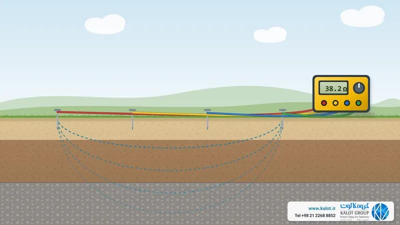
- checking the continuity of protective paths and recording results according to the project's test programme;
- reviewing SPD indicators and condition after an event or according to the maintenance programme;
- reviewing the separation distance after panels are added or cables and equipment are moved;
- for monitored devices, reviewing alerts and strike records alongside the physical inspection.
Which KALOT Group equipment is used in this design?
A product is chosen for its correct place on the drawing; a product's name alone does not make it right for every PV plant. In each project, the conductor material and size, ambient corrosion, connection method and the requirements of the design reference must be reviewed.
Franklin France ACTIVE 1D+ ESE air terminal
The suggested option to enquire about for high-count, budget-sensitive projects. It comes in four models with different ΔT values and uses a dedicated tester for performance checks. The model and number of terminals are set after calculating the protected volume and the total system cost.
Franklin France ACTIVE 4D ESE air terminal
The option with advanced monitoring features, for projects where these features help operation. In the 60 microsecond model, the tabulated radius at the same height and protection level equals that of ACTIVE 1D+60; the final choice depends on the project's need and the price enquiry.
Galvanised steel round wire and copper tape
For down conductor routes or parts of the earth network, where material, size and installation method match the design. The final choice also depends on the corrosive environment and metal compatibility.
Threaded copper-bonded earth rod
One of the electrode options for a designed earthing system. Number, depth and layout are set by soil testing and the engineering goal; a single earth rod does not complete the bonding of the whole site.
U clamp for connecting conductor to earth rod and reinforcing bar and copper C clamp
Conductor connection and branch components, at points where their use and material have been approved. For connecting a PV module frame, the part permitted by the panel or rack maker and the project specifications are the measure; not every general clamp suits a frame.
GIM ground improvement material
Considered for improving electrode-to-soil contact where design and soil testing show the need. This material does not replace better connections, protective conductors or the bonding network.
Bare copper conductor
A conductor option for part of the earthing network, bonding or down conductor, provided the cross-section and connection method are chosen to match its duty. DC cable routes and protective conductors must not be confused with each other.
Decision table for three common ground-mounted site scenarios
Scenario | Review priority | Technical decisions |
|---|---|---|
Ground-mounted site with dense rows | Mast shading, separation distance, down conductor route and maintenance access | Comparing the conventional layout and, if permitted, ESE on the actual site model; checking points outside the protected volume |
Extensive ground-mounted site with several inverter stations | Uneven terrain, long DC, AC and data cables, each station's incoming lines and the presence of people | Dividing the site into protection zones, coordinating SPDs, the earth network and bonding routes |
Extending an existing plant | Position of new rows relative to the existing LPS and earth network | Recalculating the protected volume, distances and current share; continuity testing and updating the handover drawing |
Before handover, these documents must be clear
- risk assessment report and the chosen protection level;
- protected volume plan, terminal and mast positions, shading analysis and separation distance calculation;
- DC, AC and data single-line drawing, SPD locations and the specifications each circuit needs;
- bonding drawing for frames, rails and inverters, and the relationship of the LPS to the earth network;
- connector details, materials, corrosion, initial test and periodic inspection programme.
Standards and technical sources for this guide
The binding reference for each project is set by the regulations of the place of execution and the contract specifications. This list is here to make the scope of each document clear; a standard's introduction page does not replace its full text for execution calculations.
Reference | Role in a PV project |
|---|---|
Lightning risk assessment and choosing protection measures for the structure | |
External protection, separation distance and touch and step voltage hazard | |
Protecting electrical and electronic systems from the electromagnetic effects of lightning | |
Dedicated technical report on lightning and surge protection in PV power supply systems | |
Requirements for PV electrical installations; replaces the 2017 edition | |
Earthing arrangements, protective conductors and protective bonding | |
Requirements and tests for SPDs made for the DC side of a PV system | |
Principles of selecting, installing and coordinating SPDs for rooftop and ground-mounted PV | |
Product requirements for SPDs in low-voltage AC circuits | |
Selecting and coordinating SPDs in AC circuits | |
Requirements for SPDs in data, telecommunication and signal networks | |
Design, testing, inspection and maintenance method for ESE systems where they are accepted | |
American references for LPS and PV installations, on projects subject to US regulations; acceptance of ESE is reviewed separately |
Conclusion
Protecting a ground-mounted solar plant is not a "single product"; it is an engineering decision across site risk, the external protection method, the actual protected volume, separation or bonding, DC, AC and data SPDs and the earth network. Our project experience at KALOT can help in reviewing drawings and choosing a solution. For sites that need several terminals and are budget-sensitive, ACTIVE 1D+ is the more economical option for an initial enquiry, and ACTIVE 4D is considered when advanced monitoring has practical value. The final number and model must be weighed against the real geometry and total system cost.
Review your ground-mounted plant design with KALOT
Share your panel row plan, inverter station locations, cable routes, soil test results and earthing system data with the specialists at KALOT Group. With our project experience across about 140 ground-mounted projects in Iran, we can review the options for direct lightning strike protection, the right model and number of ACTIVE 1D+ units, bonding and earthing equipment for your site conditions.