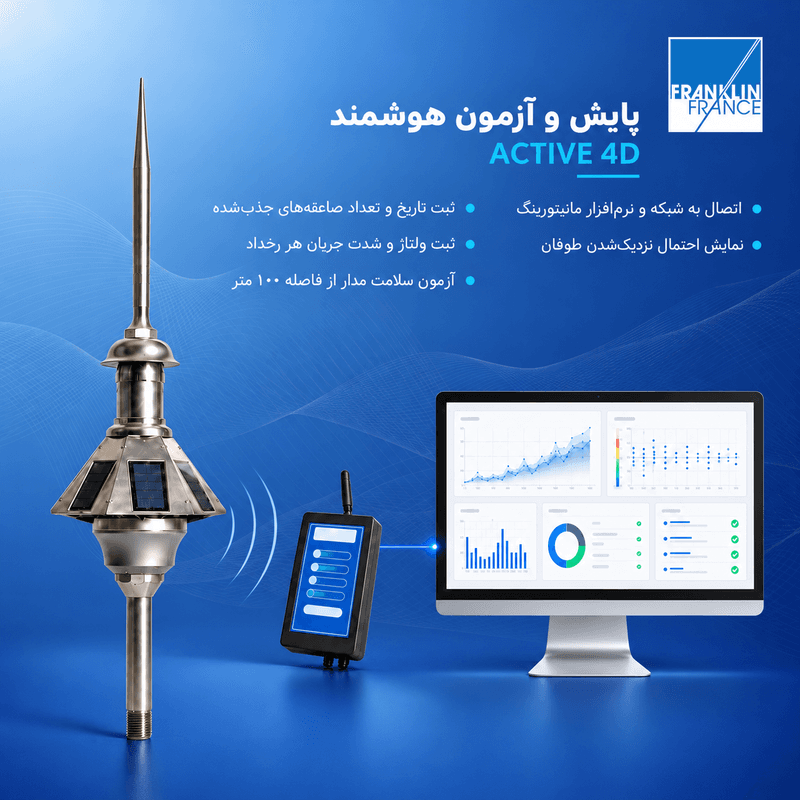
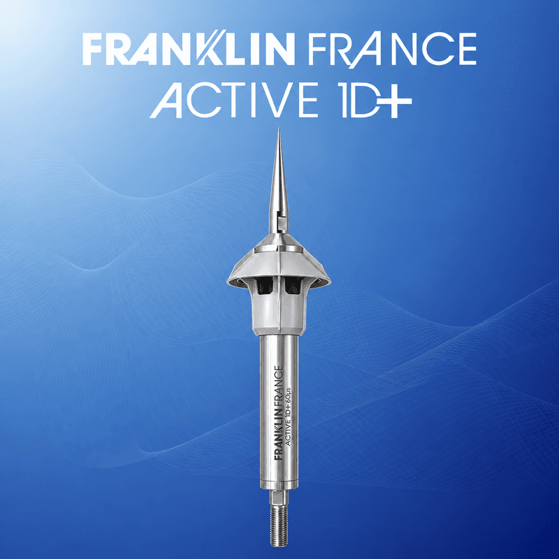
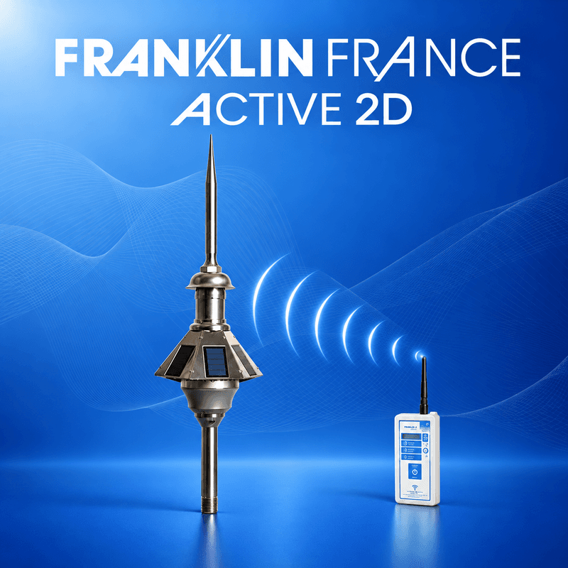
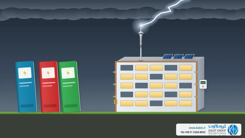
This page is an installation checklist for NF C 17-102 (2011 edition) for ESE air terminals. We have kept each point short and given the clause number wherever it was available. If you want to know what ΔT is, how the protection radius is calculated and what the standard covers, read our guide to ESE air terminals and NF C 17-102 first.
Design and position of the air terminal
1. Establish the protection level first. A risk assessment (Annex A of the standard or IEC 62305-2) sets protection level I to IV. Without a protection level, no protection radius figure means anything. We carry out lightning risk assessments.
2. Ask for ΔT from the Annex C test report. A device with ΔT below 10 microseconds does not count as ESE, and in calculations ΔT is capped at 60 microseconds, even if the test gave a higher figure.
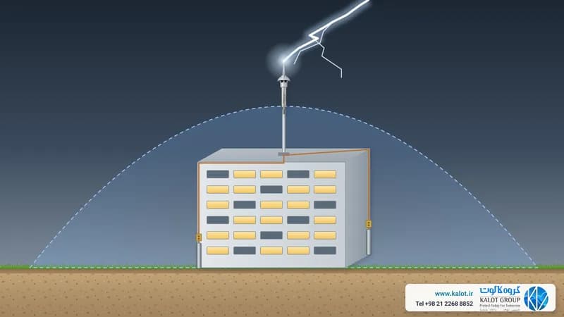
3. Calculate the protection radius with the formula and for the real height. Rp depends on ΔT, on the height h of the air terminal tip above the furthest surface to be protected, and on the protection level. You will find the formula and full table in our protection radius guide.
4. Air terminal tip at least 2 m above every item in the protection zone (clause 5-2-5). Antennas, cooling towers, chimneys, ventilation units and any other installation inside the protection zone of the air terminal must be at least 2 m below its tip.
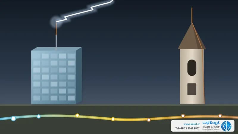
5. Air terminal at the highest point of the structure, on a firm mast. The mast must stay stable against wind and vibration, and tall masts are guyed according to the manufacturer's instructions. The galvanised telescopic mast and arched clamp are made for this job.
6. Bond antenna masts and metal roof installations to the system. The standard has special provisions for antennas. An antenna mast on the roof is connected to the conductors of the lightning protection system, so that lightning current does not enter the building along the antenna cable.
Down conductors
7. Each air terminal has at least two down conductors (clause 5-3-2). These two conductors connect the air terminal to the earthing system along two separate routes, preferably on different facades of the building.
8. Keep two conductors on one facade well apart. If both must run on the same facade, manufacturers, citing the standard, ask for a spacing of at least 10 m.
9. Conductor material and dimensions as per the component standard table (clause 5-3-6). For the material and dimensions of the down conductor and earth conductor, the 2011 edition refers to Table 1 of BS EN 50164-2 (today EN 62561-2). The minimum cross-section is 50 mm², and tape is preferred to round conductor, for example copper tape or tinned copper tape.
10. A short, straight conductor route on the outside of the building (clause 5-3-3). The down conductor preferably runs on the outermost part of the facade, comes down as straight as possible, and does not pass beside or inside plumbing or electrical cabling.
11. Change direction with a gentle bend, not a sharp angle. Wherever the conductor has to change direction, the bend radius should be at least 20 cm and the conductor should never run upwards. Under the impulse current of lightning, a sharp angle behaves like a knot.
12. Three clamps per metre (clause 5-3-3). The down conductor is fixed to the facade with three clamps per metre, which means one clamp about every 33 cm, using a brass tape-to-wall clamp or stainless steel tape-to-wall clamp and, for round conductor, a stainless steel conductor-to-wall clamp.
13. Mechanical guard up to 2 m above ground (clause 5-3-3). To prevent impact and damage, the down conductor runs inside a metal or polyethylene guard up to at least 2 m above ground.
14. Each down conductor has a test joint. Each down conductor route connects to the earthing system through a test joint (disconnect link), so that its earthing can be measured separately. The earth symbol is marked on the test joint.
15. A lightning strike counter on one of the conductors. The lightning strike counter is installed above the guard, close to the test joint. Manufacturers recommend it, because each new count means a strike and a need for inspection.
16. The building's metal frame in place of a down conductor (clause 5-3-9). If the building's metal frame is continuous and meets the conditions of the standard, it can replace all or part of the down conductor. In that case the top of the frame connects to the lightning protection system and the bottom to the earthing system.
17. Composite, glass or stone facades (clause 5-3-9). In these buildings the down conductor can be installed behind the facade. The conductor is then connected and bonded to the facade's metal substructure at its start and end.
18. Keep the separation distance, or bond. The down conductor must stay away from cables, pipes and metal parts inside the building by at least the separation distance s = ki × (kc / km) × l. For two down conductors, the factor kc is 0.75. If this distance cannot be achieved, the metal part is bonded to the conductor.
Structures taller than 60 m
19. Above 60 m: additional protection and four down conductors (clause 5-2-3-4). In structures taller than 60 m, the top 20% of the height needs special provisions against side strikes on the facade, and at least four down conductors are installed, on four different facades where possible.
20. Above 120 m: additional protection at every point above 120 m. In structures taller than 120 m, on top of the provisions for above 60 m, every point higher than 120 m also needs additional protection. Leave the design of these structures to a specialist: lightning protection system consulting and design is one of our services.
Earthing system
21. One earthing for each down conductor, below 10 ohms (clause 6-1). The desired earth resistance of each down conductor is 10 ohms at most. Measure the resistance with the test joint open. We explain the calculation method in calculating earth electrode resistance.
22. Low-inductance layout: crow's foot or three earth rods in a triangle. Lightning current is extremely fast, so earthing needs low inductance as well as low resistance. The common layouts are either the "crow's foot" (three buried conductors spreading outwards from the building) or three earth rods in a triangle, spaced further apart than the length of an earth rod and linked by a conductor buried about 50 cm deep. Underground joints last when made with KALweld® exothermic welding.
23. If 10 ohms cannot be reached. In high-resistivity soils, the total electrode length is increased. Manufacturers, citing the standard, mention at least 160 m of horizontal or 80 m of vertical electrode for level I, and 100 or 50 m for the other levels. Ground improvement materials are also permitted.
24. Bond all earthing to the building's earthing. The air terminal earthing is not left separate from the building's earthing: it is bonded to it through a removable connection in an earth inspection pit. Manufacturers also recommend a spacing of at least 5 m between the electrodes and buried metal pipes or cables.
Internal protection and inspection
25. Bonding, SPDs and periodic inspection. An air terminal only protects the building from a direct strike. The equipment inside also needs bonding and equipotentialisation (bonding) and the installation of power SPDs and data SPDs. Under clause 8 of the standard, the system is inspected periodically and after every strike, and the condition of the air terminal is tested, with a remote tester on the models we supply. We carry out periodic testing and inspection.
Summary table: which point relates to which component?
Part | Related points | Suitable parts |
|---|---|---|
Air terminal and mast | 1 to 6 | |
Down conductor and clamps | 7 to 12 and 16 to 18 | |
Bottom of the down conductor | 13 to 15 | |
Earthing system | 21 to 24 | Copper-bonded earth rod, earth inspection pit, ground improvement materials |
Internal protection | 25 |
These points do not replace project design: the designer sets the number of air terminals, mast height, conductor routes and earthing type for each building. For consulting, design or a price enquiry, send the building's drawing or dimensions to our specialists, or reach us through our contact us page.