
Move your pointer over the image to zoom in
Complete Product Overview
Two-piece stainless steel clamp for fixing conductor to walls
Last updated:
The KALOT two-piece stainless steel clamp holds a round conductor on a wall. It is the part that, in lightning protection and earthing installations, keeps a 50 and 70 mm² down conductor straight and firm on the building façade from the roof to near ground level. The clamp is made of two stainless steel parts: a base plate fixed to the wall with one screw and wall plug, and a formed cover with the raised name KALOT that holds the conductor in its groove with two screws. A U-slot at one end of the cover makes installation simpler, especially at height.
A straight, firm and durable down conductor on the façade
A down conductor must stay fixed along its whole route so that it does not move in the wind or stray off its path. The KALOT two-piece stainless steel clamp holds a 50 or 70 mm² round conductor between a grooved cover and a base plate, and fixes to the wall with one screw and wall plug.
- Round conductor, 50 and 70 mm²
- Cover and base plate in stainless steel
- Wall fixing with one screw and wall plug
- Cover with U-slot for quick installation
Two-piece construction
The base plate stays on the wall while the cover holds the conductor. Opening the cover for inspection or conductor replacement leaves the clamp's wall fixing untouched.
All stainless steel
The cover and base plate are stainless steel, with no coating to wear away through scratches or time, which suits building façades exposed to the weather.
Threaded insert in the base plate
The cover screws fasten directly into press-fit inserts in the base plate, so all the work is done from the front of the façade and no rear nut is needed.
U-slot for work at height
Only one screw per clamp is fully removed and refitted, and the cover stays hanging on the other screw during installation, making work on scaffolding simpler and safer.
KALOT drawing and installation guide
Dimensional drawing, exploded view, installation steps and an execution schematic on a down conductor, as PDF and SVG for designers and installers.
Technical Product Information
Click to view enlarged
Feature | Value |
|---|---|
Product type | Two-piece holder clamp for round conductors on walls (down conductors and surface-run conductors) |
Suitable conductor | Round stranded conductor, 50 and 70 mm² (about 9 to 10.7 mm in diameter) |
Cover and base plate material | Stainless steel |
Components | Formed cover + base plate with two press-fit threaded inserts + two countersunk cross-head screws |
Approximate dimensions | Cover and base plate 80 × 25 mm; sheet about 2 mm; cover height about 9 mm |
Screw centre distance | 56 mm |
Wall fixing | One screw and wall plug through the countersunk centre hole of the base plate, to suit the wall material |
Cover | A hole at one end, a U-slot at the other; raised name KALOT on the groove |
Mounting surface | Concrete, brick and block walls; parapets and vertical surfaces |
Role in the system | Mechanical conductor holder; electrical connection of conductors is made with connection clamps |
Application | Down conductors and round conductors in lightning protection, earthing and bonding systems |
Reference standards | IEC 62561-4 (conductor holders) and IEC 62305-3 (design and installation of the protection system) |
Dimensions are approximate and based on the KALOT manufacturing drawing and a product sample. For detailed design or project orders, please ask the KALOT Group technical team for the final specifications.
Click to view enlarged
The drawing shows the front and side views of the cover and base plate and a section of the clamp fitted on a conductor: length and width about 80 × 25 mm, sheet about 2 mm, cover height about 9 mm and screw centre distance 56 mm.
Download the drawing: PDF · SVG (vector)
Click to view enlarged
Clamp components
- Base plate: a flat stainless steel strip with three holes. The centre hole is countersunk and takes the wall screw. The two end holes have press-fit threaded inserts, and the cover screws fasten directly into them, with no rear nut needed.
- Cover: formed stainless steel sheet with a half-round groove in the middle that sits on the conductor, and the raised name KALOT on it. One end of the cover has a hole and the other a U-slot.
- Two countersunk cross-head screws: these fasten the cover to the base plate and hold the conductor between the cover's groove and the base plate.
Because the wall screw sits under the conductor at the centre of the plate, fitting and removing the cover leaves the clamp's wall fixing untouched. For inspection or conductor replacement, the cover opens and the base plate stays where it is.
The U-slot lets the installer loosen the screw on the slot side by just a few turns, slide the slot under its head and lay the cover over the conductor. That way only one screw per clamp is fully removed and refitted, and the cover stays hanging on the wall during the work. This small detail makes work on scaffolding or on ropes faster and less risky.
Why stainless steel?
Down conductor clamps spend years exposed to rain, sun, pollution and façade moisture. The resistance of stainless steel lies in the metal itself, not in a coating that wears away with scratches or time. It stands up well to atmospheric corrosion, and its bright look stays clean and uniform on the building façade.
Contact between a copper conductor and a stainless steel clamp is common in normal atmospheric conditions. In highly corrosive environments (industrial, coastal or chemical), or if the conductor is aluminium or galvanised steel, check material compatibility before work begins with the system designer and the KALOT Group technical team.
Click to view enlarged
Where it fits in the lightning protection system
This clamp is fitted along the down conductor route, from the roof edge to the test joint near ground level, and on round conductors on parapets and vertical surfaces. The roof conductor passes the edge of the building and reaches the down conductor, and the down conductor connects to the earthing system through the test joint.
Installation steps
- Mark the conductor route and the position of each clamp on the façade according to the system drawing.
- Drill the wall hole to suit the wall plug, clear out the dust and insert the plug. Choose the screw and wall plug to suit the wall material (concrete, brick, block).
- Place the base plate at right angles to the conductor route and fasten the screw through the centre hole until its head seats in the countersink and the plate sits firmly on the wall.
- Turn the slot-side screw a few turns into its insert without fully tightening it.
- Run the conductor straight and free of twists over the centre of the base plate.
- Slide the cover's U-slot under the head of the loosened screw and lay the cover over the conductor so that its groove sits on the conductor.
- Fit the second screw through the cover hole into its insert, then tighten both screws gradually and evenly until the conductor is not loose in the clamp. Avoid overtightening, which can deform the sheet.
- Finally, test the conductor: it must not slip or turn in the clamp, and it must stay straight in line with the clamps before and after it.
Clamp spacing along the conductor route
The system designer sets the number and spacing of holders. Common guidance from makers of lightning protection equipment, based on IEC 62561-4 and IEC 62305-3, recommends these spacings for stranded conductors:
Installation location | Typical holder spacing |
|---|---|
Stranded down conductor, up to 20 m high | Maximum about 1 m |
Stranded down conductor, above 20 m | Maximum about 0.5 m |
Stranded conductor on roofs and parapets | Maximum about 0.5 m |
Before and after a bend, connection clamp or expansion piece | About 0.3 m |
On tall façades, in windy areas and where the conductor is within reach or exposed to impact, closer spacing is chosen. Run the down conductor as straight and vertical as possible, and avoid loops and sharp bends.
Inspection and maintenance
During periodic inspections of the lightning protection system, check the clamps for loose screws, a slack conductor, a shifted base plate or mechanical damage, and retighten the screws evenly if needed. The electrical continuity of the down conductor is measured at the test joint (disconnector) near ground level.
The following standards are listed to help you understand the requirements for this type of part and its place in a lightning protection system.
Conductor holder standard: IEC 62561-4
This part of the lightning protection system component series sets the requirements and tests for metallic and non-metallic conductor holders, the parts that hold air-termination conductors, down conductors and earthing system conductors on a structure. The tests include environmental ageing (salt mist and humid sulphurous atmosphere), mechanical strength testing of the holder against lateral and axial conductor forces and, for non-metallic materials, resistance to ultraviolet radiation.
System design standard: IEC 62305-3
This standard covers the design, installation, inspection and maintenance of a structure's lightning protection system, including the number and route of down conductors, running them straight and short, the location of the test joint and the fixing of conductors to the structure. The choice of clamp locations and spacing rests with the system designer.
Round conductor holding clamps for walls
Documents & Downloads
Drawings & schematics
- Approximate dimensional drawing of the two-piece stainless steel clamp for fixing conductor to walls (PDF)Language: Persian (opens in a new tab)
- Exploded view of the two-piece stainless steel clamp for fixing conductor to walls (PDF)Language: Persian (opens in a new tab)
- Installation steps for the two-piece stainless steel clamp for fixing conductor to walls (PDF)Language: Persian (opens in a new tab)
- Installation schematic on the down conductor of a lightning protection system (PDF)Language: Persian (opens in a new tab)
Frequently Asked Questions
Which conductors is this clamp suitable for?
For round stranded conductors with a cross-section of 50 and 70 mm² (about 9 to 10.7 mm in diameter), the most common sizes for down conductors and round conductors in lightning protection and earthing systems. For another size, please check with KALOT Group before ordering.
Does this clamp connect two conductors together?
No. This clamp is a mechanical holder that keeps the conductor fixed to the wall. To connect two conductors electrically, use connection clamps, such as the three-way conductor-to-conductor clamp.
How far apart should the clamps be on a down conductor?
The system designer sets the final spacing. Common guidance for a stranded down conductor is a maximum of about 1 m up to a height of 20 m, about 0.5 m above 20 m, and about 0.3 m before and after bends and connection clamps.
What is the U-slot at one end of the cover for?
With the U-slot, you do not need to remove both screws fully: the screw on the slot side is loosened by just a few turns, the slot goes under its head and the cover is laid over the conductor. This speeds up work at height and makes it less likely that a screw or cover will fall.
How do we choose the wall screw and wall plug?
The base plate is fixed to the wall with one screw through the countersunk centre hole. Choose the screw and wall plug to suit the wall material (concrete, solid or hollow brick, block), preferably in a corrosion-resistant material so that they match the life of the clamp.
Why stainless steel and not brass?
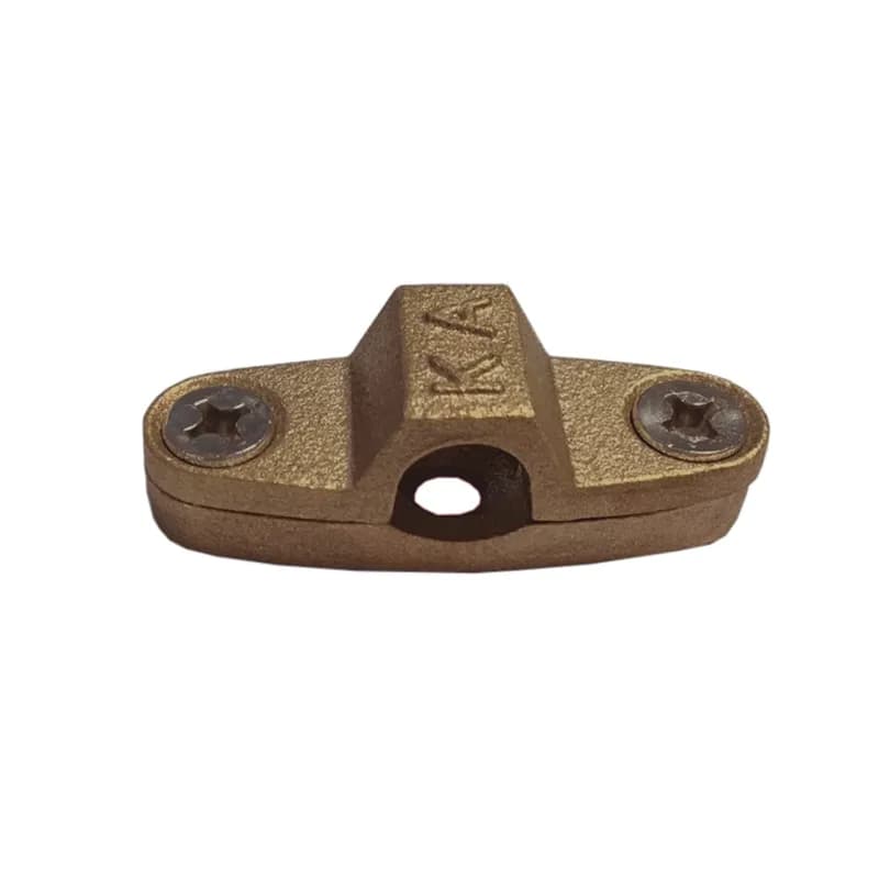
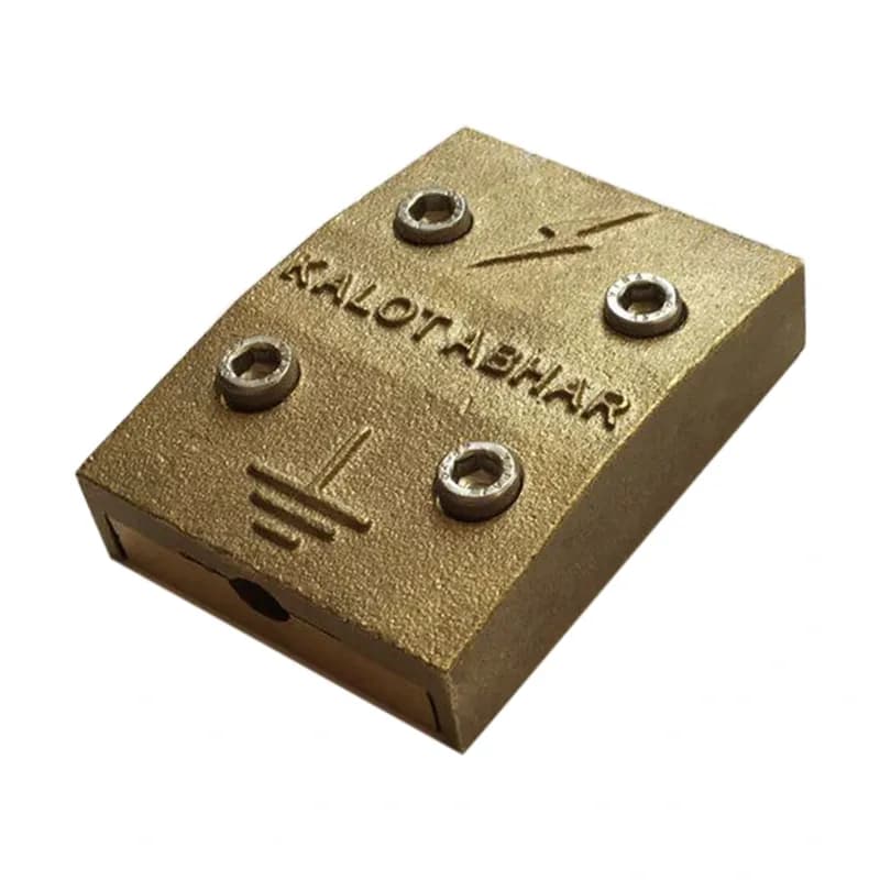
Both are used to hold a round conductor on a wall. The stainless steel clamp is lighter, its resistance does not depend on a surface coating, and it looks bright and uniform on the façade. The two-piece brass clamp has a heavier cast body and is also available for conductors up to 95 mm². The choice depends on the conductor size, environmental conditions and project specification.
Is it also suitable for tape conductors?
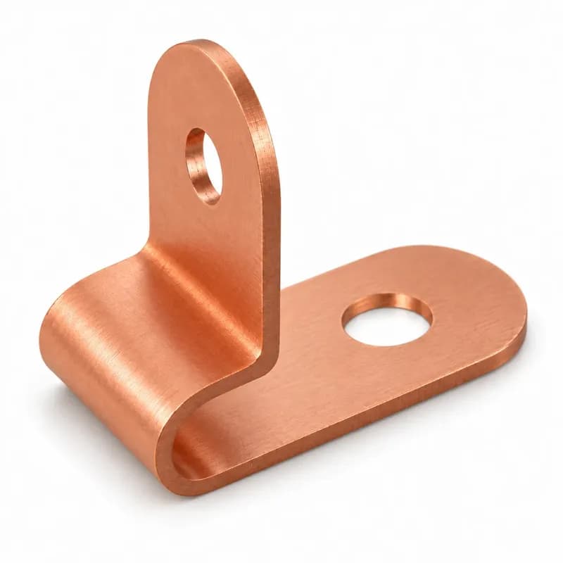
No. The groove in the cover is designed for round conductors. For tape, use this clamp's sister product, the two-piece stainless steel clamp for fixing tape to walls, or the KALOT one-piece tape-to-wall clamp and two-piece brass clamp for fixing tape to walls.
Can it also be used on a roof?
This clamp is designed for vertical surfaces such as façades and parapets. On a flat roof, the conductor is usually run on roof support bases.
Which standard applies to conductor holders?
IEC 62561-4 sets the requirements and tests for conductor holders in lightning protection systems, and IEC 62305-3 covers the design and installation of the whole system, including conductor routing and fixing.
Have a Technical Question?
KALOT Group's technical experts are ready to answer your questions about lightning rods and earthing systems.