Short answer: Protective earth (PE) means connecting the metal enclosure of equipment to the protective conductor, so that if the insulation fails and the enclosure becomes live, fault current has a path and the breaker or fuse opens the circuit. Its purpose is to protect human life. Electrical earth, in common Iranian usage, means earthing the neutral (star) point of a transformer or generator, which Iranian regulations call "operational earthing". Functional earth (FE) is a connection needed for equipment to work correctly, for example as a voltage reference and to reduce noise, and it does not replace protective earth.
What does "electrical earth" mean in Iran?
On the Persian web and in the market, earthing a transformer's neutral point is called "electrical earth". The Safety Regulation for Earthing Systems (1401) and Topic 13 of the National Building Regulations use the term "operational earthing" for it, and call the connection of metal enclosures "protective earthing".
In the International Electrotechnical Vocabulary (IEC 60050-195), earthing a power system is called System Earthing, and it has both a functional and a protective role, because the fault current return path in TN systems also passes through this point. So the neutral point earth should not be confused with the functional earth (FE) of equipment. How the neutral and the protective conductor are separated or combined along the network determines the type of earthing system: TN-S, TN-C-S, TT and IT.
Protective earthing (PE)
Protective earth, or PE, connects the touchable conductive parts of equipment to the protective network of the installation. If the insulation fails and a metal enclosure becomes live, this connection gives fault current a suitable path so that the protective device can disconnect the faulty circuit within the required time.
Correct PE performance does not depend only on having a green and yellow wire or a low earth electrode resistance. Protective conductor continuity, fault path impedance, bonding, conductor cross-sections and coordination with the protective device must all be reviewed to suit the distribution system and project conditions.
For example, the metal enclosures of protection Class I equipment, electrical panels and industrial machinery must be connected to the protective conductor according to the design. This requirement should not be applied to every electrical device without checking, because some equipment, such as Class II appliances, is designed around double insulation and has no PE connection.
The main references on protection against electric shock and on protective conductors in low-voltage installations include IEC 60364-4-41 and IEC 60364-5-54.
How do you identify the protective conductor?
- Colour: green and yellow is reserved for PE protective conductors and PEN conductors and is used for no other conductor. We supply green and yellow copper earth wire for exactly this purpose.
- Cross-section: under IEC 60364-5-54, if the PE conductor is the same material as the phase conductor, it matches the phase size for phases up to 16 mm², is at least 16 for phases of 16 to 35 mm², and at least half the phase cross-section for phases above 35. The final size is set by the short-circuit current and the disconnection time of the protective device.
- Symbol: a protective earth terminal is marked with the earth symbol inside a circle (IEC 60417-5019), and a functional earth terminal with the earth symbol without a circle (IEC 60417-5018).
Functional earthing (FE)
Functional earth, or FE, is a connection needed for the correct operation of a device or system, and its main purpose is not protection against electric shock. It can be used to provide a voltage reference, reduce noise, control electromagnetic interference and improve the performance of electronic systems, instrumentation, industrial controls, telecommunications and data centres.
A device may need a PE connection as well as an FE terminal. In that case FE never replaces the protective conductor, and the PE connection must not be cut or removed to cure noise.
Connecting the neutral point of a transformer or generator to earth is part of the earthing arrangement of the distribution system and should not always be treated as the same thing as FE. Each connection must be designed according to its actual function, the network type and the manufacturer's requirements.
References on earthing and cabling for electromagnetic compatibility include IEC TR 61000-5-2 and, for telecommunications and IT installations, EN 50310.
Protective earth and functional earth at a glance
Protective earth (PE) relates directly to the safety of people and installations. The touchable metal enclosures of equipment are connected to the protective conductor so that, when a fault occurs, fault current has a path of suitable impedance and a protective device such as a fuse or circuit breaker can disconnect the circuit within the required time.
Functional earth (FE) exists so that equipment works correctly. It can be used to stabilise the voltage reference, reduce noise, improve signal integrity and control electromagnetic interference in electronic equipment, instrumentation, control systems, telecommunications and data centres.
In the standards, the line between the two is simple: if the functional earth connection is lost, the protection of people remains; if the protective earth connection is lost, that protection is gone.
Topic | Protective earth (PE) | Electrical earth (transformer neutral) | Functional earth (FE) |
|---|---|---|---|
What it connects to | Touchable metal enclosures | Star point of a transformer or generator | Equipment FE terminal, shield and signal reference |
Main purpose | Protecting people against electric shock | Network voltage reference and fault current path | Correct equipment operation and noise control |
If it is disconnected | Protection is lost | Voltages and network protection are disrupted | Equipment operation may be disrupted |
Identification | Green and yellow conductor; symbol 5019 | At the substation or generator location | Symbol 5018 |
The most important differences between PE and FE are:
- The main purpose of PE is protection against electric shock, fire and the consequences of electrical faults; the purpose of FE is stable operation and fewer electromagnetic disturbances.
- PE is part of the safety measures of an installation and must not be cut or removed to cure noise; FE, for its part, never replaces the protective connection of equipment.
- Current through PE matters mainly under fault conditions; in FE there may be small functional currents, noise or high-frequency components.
- The PE path must be continuous, reliable and designed for the possible fault current; the FE path must also be reviewed for length, layout, high-frequency impedance and the risk of unwanted loops, as well as electrical continuity.
- In some installations, PE and FE connect to one common bonding and earthing network, but how they connect must be decided by engineering design, the type of distribution system, the equipment manufacturer's requirements and electromagnetic compatibility considerations.
Should protective earth and functional earth be separate from each other?
There is no single answer for every project. Protective earth and functional earth have different jobs, but depending on the installation architecture, the equipment and the bonding scheme, they may connect to a common network at defined points.
Creating two completely independent earthing systems without checking the potential difference between them can be dangerous. If a device's enclosure is connected to PE and its circuit or shield to FE, the potential difference between the two networks may drive unwanted current, create noise, damage equipment or raise touch voltage. The Safety Regulation for Earthing Systems (1401) also requires a "clean earth" to be connected to protective earth. Branches can have separate conductors, but they all meet at the main earth bar, for example an earth bar with a disconnect link, which also allows temporary separation for measurement. We go into more detail in our article Earthing and its types.
In a sound design, the safety requirements of PE always come first. The FE path can be designed to suit the equipment's needs and electromagnetic compatibility requirements, but it must not interrupt the continuity of the protective conductor or replace it. Where and how the two networks connect must also be shown on the construction drawings and tested after installation.
Two examples: a home and a data centre
Residential building
At the neighbourhood substation, the transformer's star point is connected to earth (electrical earth). At home, the metal bodies of the refrigerator, washing machine and air cooler are connected to the protective conductor through the green and yellow wire of the socket (protective earth). If a phase touches the body of the washing machine, fault current returns through the protective conductor and the breaker or fuse opens the circuit; a residual current device (RCD) adds further protection. The home's protective conductor is also connected to the building's earth electrode, for example a copper-bonded earth rod in a polyethylene inspection pit, and to the bonding of pipes and the metal frame.
Data centre and server room
Rack frames, panels and UPS enclosures are connected to protective earth to keep people safe from electric shock. Alongside this, each rack's earth bar and the shields of data cables form a common reference for the equipment (functional earth) to reduce noise and interference. All these branches meet in one bonding network and one main earth bar. For locations with a lot of IT equipment, the 1401 regulation requires a TN-S system. To protect equipment against overvoltage, a power SPD and a data line SPD are also needed (types of SPD).
Key principles in PE and FE design
- First establish the distribution system and earthing arrangement, such as TN, TT or IT, because the way fault current flows and protective devices operate depends on it.
- The cross-section, material, route and connections of the protective conductor must suit the possible fault current and the disconnection time of the protective device.
- All touchable conductive parts and relevant metal components should be connected to the PE network according to the protective bonding scheme.
- In FE design, low-frequency electrical resistance is not the only criterion; path length, inductance, contact area, cabling method and high-frequency impedance also matter.
- FE paths and shields must be installed according to the equipment manufacturer's instructions and the electromagnetic compatibility plan; connecting without a plan may create unwanted loops and noise.
- Connections must be protected against corrosion, loosening and mechanical damage and remain accessible for periodic inspection and testing; standard earth clamps and exothermic welding make lasting connections.
- As-built drawings, conductor labelling, measurement results and PE and FE connection points must be documented and kept on file.
Common applications of protective earth and functional earth
Protective earth is used on electrical panels, industrial machinery, equipment with metal enclosures, cable trays and ladders, electric motors, transformers, distribution systems and any other parts that people could reach if the insulation fails.
Functional earth is mostly used in instrumentation, PLC and industrial control systems, telecommunications equipment, data centres, computer networks, uninterruptible power supplies, variable speed drives, measuring equipment and sensitive audio and video systems.
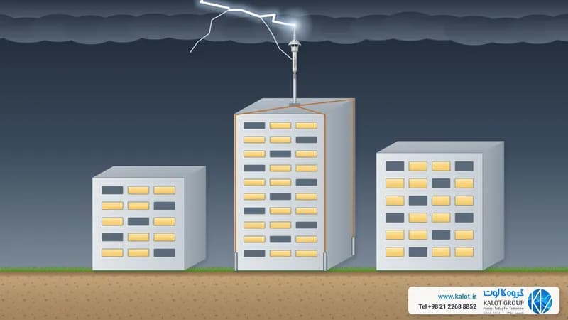
In complex installations, PE and FE design must be reviewed together with bonding, lightning protection, transient overvoltage protection equipment and cable routes. Deciding on each of these separately may disrupt the performance of the whole system.
Common mistakes when installing PE and FE
- Treating the earth resistance figure as the only measure of system quality, when path continuity, fault loop impedance, bonding and the operating time of the protective device matter too. If electrode resistance is high in high-resistivity soil, GIM ground improvement material helps, but all these other points must be right as well.
- Using FE instead of PE, or cutting the protective conductor to get rid of noise; this can put people's safety at risk.
- Connecting neutral and PE at several points outside the locations the design allows; this can drive unwanted currents through the protective conductor and metal parts.
- Creating several earth connection points without a drawing or an analysis of the current path; the result may be loops, more noise or potential differences.
- Using long, thin conductors for paths sensitive to high frequencies; such a path may have low resistance yet lack a suitable impedance against high-frequency noise.
- Neglecting corrosion of connections, contact between dissimilar metals, loose clamps and mechanical damage.
- Installing without coordinating with the equipment manufacturer's instructions, the electrical drawings, the lightning protection design and the placement of overvoltage protection equipment.
- Handing over the system without testing, recorded measurement results, labelling and as-built drawings.
Standards related to protective earth and functional earth
Earthing systems must be designed and installed according to national regulations, project specifications, equipment manufacturers' instructions and recognised standards. The most important international references include:
- IEC 60364-4-41: requirements for protection against electric shock and protective measures in low-voltage electrical installations.
- IEC 60364-5-54: requirements for earthing arrangements, protective conductors and protective bonding conductors.
- IEC TR 61000-5-2: guidance on earthing and cabling to improve the electromagnetic compatibility of equipment and systems.
- IEC 60050-195: the official definitions of protective earthing, functional earthing and system earthing.
- In Iran: the Safety Regulation for Earthing Systems (1401), mandatory for workplaces covered by the Labour Law, and Topic 13 of the National Building Regulations.
Each standard must be chosen and applied to suit the type of installation, voltage, environmental conditions, distribution system, legal requirements at the project location and the valid edition of the document. Citing a standard alone does not replace engineering design, calculation, inspection and testing.
Testing and maintaining the earthing system
An earthing system's performance is not confirmed by a visual check or a single earth resistance reading. The scope of testing must suit the type of installation and the protection design, and can include:
- Inspecting routes, connections, identification markings and the mechanical protection of conductors.
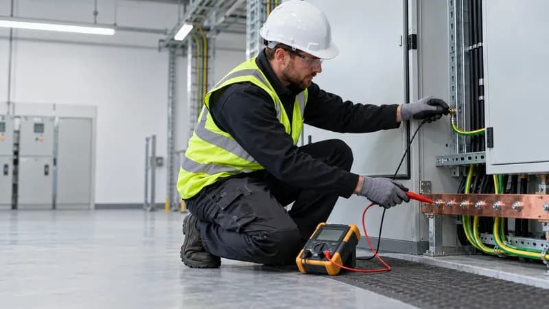
- Continuity testing of protective and bonding conductors.
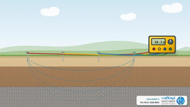
- Measuring earth electrode resistance, where it is relevant to the design (measurement method and common values).
- Checking fault loop impedance and its coordination with the protective device.
- Functional testing of residual current devices, where used.
- Checking FE connections, shields and bonding against functional and electromagnetic compatibility requirements.
- Recording results, comparing them with reference values and repeating the tests at intervals that suit operating conditions.
We also carry out earthing system testing and measurement, earthing and bonding system design and installation of earthing, air terminals and SPDs.
Conclusion
Protective earth (PE) and functional earth (FE) are two different but related concepts. PE is an essential part of protection against electric shock and the consequences of electrical faults, while FE serves the correct operation of equipment, a suitable reference and the control of electromagnetic disturbances. Electrical earth, meaning the earthing of a transformer's neutral point, is also part of the network's earthing arrangement and has both roles.
Neither replaces the other. A successful system must address safety, bonding, the fault current path, electromagnetic compatibility, protection against lightning and overvoltage, environmental conditions and equipment needs within one coordinated design. The system must also be designed, installed and tested by qualified people according to project requirements. For advice and enquiries about earthing equipment, reach our specialists through the contact us page.