Short answer: TN-C-S combines the TN-C and TN-S systems. A shared PEN conductor runs from the transformer to the building entrance, and at the incoming board it splits into neutral (N) and protective conductor (PE). From that point on, these two conductors are never joined again. Most buildings fed from the city distribution network work on this system.
Structure of the TN-C-S system
The TN-C part is usually the distribution network and the TN-S part is the wiring inside the building. At the separation point, the PEN is connected to the building's main earth bar and the neutral leaves from there as a separate conductor. The same bar is also connected to the building's earth electrode and to the bonding of pipes and the metal structure.
Rules for the PEN split point
- Once, and one way only: under IEC 60364-5-54, once separated, N and PE must never be joined again. If neutral and earth are reconnected in sub-distribution boards, neutral current spreads through the protective conductor and the structure, and the residual current device no longer works properly.
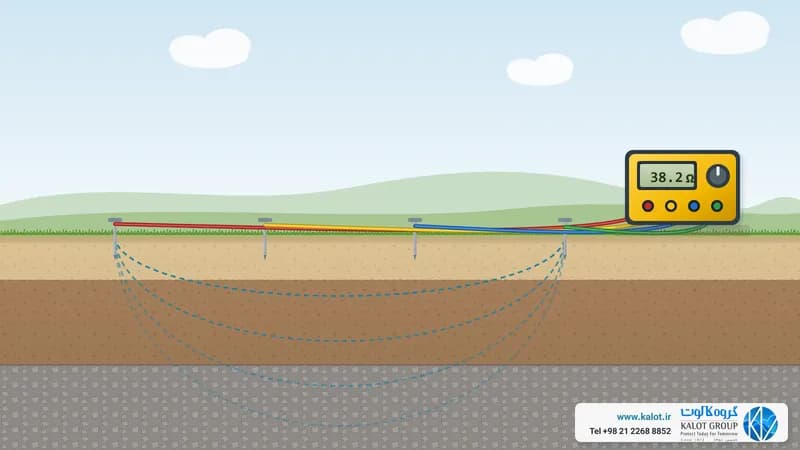
- Earthing at the entrance: connecting the split point to the building's earth electrode reduces the effect of a possible network PEN break. Article 116 of the Earthing System Safety Code (1401) requires the earth resistance at this point to be below 2 ohms. To reach that figure, see protective earthing system design and earth resistance measurement.
- A bar with an accessible connection: an earth bar with a disconnect link lets you measure the electrode resistance without opening the main connections.
The risk of a PEN break in TN-C-S
If the network PEN breaks before the split point, the building's neutral current has no path except the protective conductor, the earth electrode and metal pipes, and equipment bodies can take on a dangerous voltage. A good earth electrode at the entrance and main bonding reduce this voltage but do not bring it to zero, so the soundness of the PEN connection in the network and at the metering point must be checked too.
Benefits and uses of TN-C-S
- The network section needs one conductor fewer, and inside the building all the benefits of TN-S are kept.
- The residual current device works properly after the split point.
- Uses: residential, office and commercial buildings fed from the city network.
Where TN-C-S sits among earthing systems
Each system's name has two or three letters. The first letter says how the source (the transformer star point) relates to earth: T means directly earthed, and I means isolated from earth or earthed through a high impedance. The second letter says where the metal enclosures of equipment connect: N means to the earthed point of the source through a protective conductor, and T means to the site's own earth electrode. A third letter appears only in the TN family: S means neutral and protective conductor are separate, and C means both share one conductor, called PEN.
System | Neutral and protective conductor | Protection against electric shock | Where you find it |
|---|---|---|---|
Separate from source to load | Circuit breaker or fuse, with Zs × Ia ≤ U0 | Factories and large buildings with their own substation | |
One PEN conductor | Circuit breaker or fuse; a residual current device will not work | Distribution networks and older installations | |
TN-C-S | PEN up to the intake, then separate | Circuit breaker or fuse, plus a residual current device after the split point | Most buildings fed from the public network |
Neutral from the network; protective conductor to the site electrode | Residual current device, with RA × IΔn ≤ 50 V | Buildings and installations far from the network or on a separate earth | |
Source isolated from earth; enclosures on the site electrode | Insulation monitoring for the first fault, disconnection on the second | Operating theatres, mines and industries where sudden loss of power is not acceptable |
We give the overall picture in types of earthing systems.
At KALOT Group we carry out earthing and bonding design and earthing system measurement and testing, and we offer the components, from copper-bonded earth rods and earth bars to green and yellow earth conductors and polyethylene inspection pits. To choose the right system, send our engineers your single-line diagram and supply type, or get in touch through our contact page.