Short answer: there is no single standard for the earthing system; each part has its own reference. In Iran, the references to consult include Part Thirteen of the National Building Regulations, the Ministry of Labour safety regulation for earthing systems (1401) and the guideline for earthing systems in distribution networks. Internationally, IEC 60364 is used for low-voltage installations, IEC 61936-1 and EN 50522 or IEEE 80 for substations and high-voltage installations, IEC 62305 for lightning, IEC 62561 for components, IEEE 81 for measurement and BS 7430 as a practical guide to earthing.
The design and installation of the earthing system is one of the most important parts of electrical installation safety. Its job is not only to carry fault current into the earth. It must also prevent dangerous touch and step voltages, provide the conditions protective devices need to operate correctly, and keep the metal parts of the building and equipment at the same potential as far as possible.
That is why the earthing system should not be reduced to one earth pit or to reaching a certain earth resistance figure. A complete earthing system includes earth electrodes, protective conductors, the earthing conductor, the main earth bar, connections, bonding of metal parts, and an inspection and testing programme.
The most important earthing system standards in Iran
In building and industrial projects in Iran, the reference should be chosen according to the type of installation, the voltage level, the contract documents and the requirements of the approving authority. The most important references are:
- The latest issued edition of Part Thirteen of the National Building Regulations;
- The safety regulation for earthing systems, approved in 1401 by the Supreme Council for Technical Protection and, under the Labour Law, mandatory for all workplaces covered by that law; it requires earth additive materials to be tested to national standard INSO 18499-7 (standard for ground improvement materials);
- The valid parts of Iranian national standard series No. 1937, titled Electrical Installations of Buildings;
- National standard INSO 23064 for foundation electrodes (foundation earthing);
- Publication or Code 110 of the Plan and Budget Organisation, where it is named in the contract documents;
- The guideline for earthing systems in distribution networks from Tavanir and the power distribution companies;
- Dedicated standards and guidelines of the oil, gas, petrochemical and telecommunications industries and of other client organisations.
Check the validity and latest edition of these documents with the official authorities before design or tendering.
International reference standards
For low-voltage installations, the IEC 60364 family is among the most important references for earthing system design. Its most widely used parts are:
- IEC 60364-4-41 for protection against electric shock and automatic disconnection of supply;
- IEC 60364-5-54 for earthing arrangements, protective conductors and bonding;
- IEC 60364-6 for inspection, initial verification and periodic testing of installations.
For medium- and high-voltage installations, IEC 61936-1 is used, and in Europe the earthing systems of these installations are designed to EN 50522 (2022 edition). For substation earthing grids, IEEE Std 80 may also be chosen as the contractual reference, depending on the project specification; its 2013 edition has been in "inactive-reserved" status since 2024, and a new edition is being drafted. Methods for measuring soil resistivity, earthing system impedance, and touch and step voltages are described in IEEE Std 81-2025.
BS 7430 (2026 edition) is also a comprehensive practical guide to protective earthing, from choosing electrode material and dimensions to the resistance calculation formulas (electrode resistance formulas).
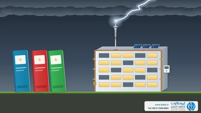
In projects with a lightning protection system, the IEC 62305 standards (IEC 62305-3 for structure protection) apply to risk assessment, lightning protection system design, bonding and the protection of electrical and electronic equipment (lightning protection standards).
The IEC 62561 family for system components
The IEC 62561 family sets the requirements and tests for earthing and lightning protection components. When you buy, ask for each part's conformity documents against the relevant section:
- IEC 62561-1, connection components: earth clamps and connections;
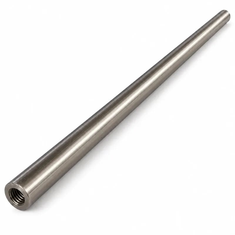
- IEC 62561-2, conductors and earth electrodes: copper-bonded earth rods, copper tape and conductors;
- IEC 62561-4, conductor fasteners: wall clamps and fittings;
- IEC 62561-5, electrode inspection pits: polyethylene inspection pit;
- IEC 62561-6, lightning strike counters: lightning strike counter;
- IEC 62561-7, ground improvement materials: GIM resistance-reducing material.
Must earthing system resistance always be below 2 ohms?
No. Contrary to a common belief, a figure such as 1 or 2 ohms is not a general, sufficient safety criterion for every building and project. The acceptable value of earth resistance or impedance depends on the network type, the fault current, the clearing time of the protective device, soil conditions and the permitted touch voltage. The 1401 regulation also asks for 2 ohms only in a specific case: the point where neutral and protective conductor separate at sites with no dedicated substation.
In a TN system, protection performance is checked mainly through the fault loop impedance: Zs × Ia ≤ U0. In a TT system, what matters is the relationship between electrode resistance, the operating current of the protective device and the touch voltage limit: RA × Ia ≤ UL.
In substations and industrial sites, earth potential rise and touch and step voltages must be calculated as well as the resistance of the earthing grid. So a system can have low resistance and still be unsafe because of incomplete bonding or poor potential distribution. We explain how these characteristics are determined in our article on protective earthing system specifications.
Soil Resistivity Measurement
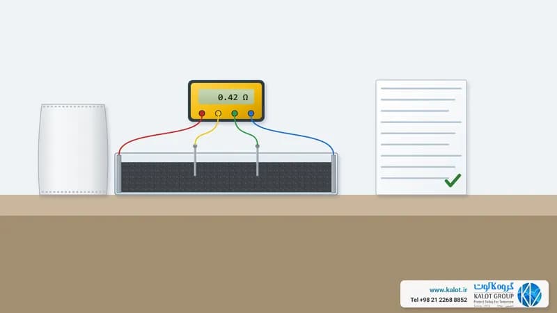
An earthing grid should be designed on real soil data. Soil resistivity changes with moisture, temperature, soil type, depth and season. The four-electrode Wenner method is one of the common ways to measure it (how to measure soil resistivity).
It is best to measure in several directions and at several electrode spacings so that different soil layers can be identified. A design based on a single measurement, or on a test made straight after rainfall, can give an unrealistic result. Soil resistivity measurement is one of our services.
Once the soil has been assessed, a suitable arrangement can be chosen from a foundation electrode, a perimeter ring, a meshed grid, vertical earth rods or horizontal conductors. In many new buildings, combining a foundation electrode with a perimeter ring is more effective and more reliable than installing a single earth pit.
Key points in design and installation
The following should be checked in the design and installation of an earthing system:
- Network type and TN, TT or IT arrangement;
- Short-circuit current and protection operating time;
- Thermal and mechanical cross-section of conductors;
- Corrosion and the compatibility of buried metals;
- Bonding of the structure, pipes, cable trays and equipment enclosures (bonding);
- Coordination of earthing with lightning protection, SPDs, telecommunications and instrumentation;
- Access to test points and connections;
- Preparing as-built drawings and recording buried connections.
The adiabatic equation S = I√t / k can be used to determine the cross-section of protective conductors. Even so, the minimum mechanical cross-section, corrosion conditions and the requirements of the lightning protection system must be reviewed separately.
The choice of copper, copper-bonded steel, galvanised steel or stainless steel should take account of soil conditions and neighbouring metals. Direct contact between incompatible metals can cause galvanic corrosion and shorten system life (earth electrode material).
Ground improvement materials must also be stable, non-corrosive and backed by valid test documents. IEC 62561-7 sets the requirements for these materials. Salt or corrosive substances may lower the initial resistance, but in the long term they can damage electrodes and the environment.
Inspecting and testing the earthing system
After installation, measuring the resistance of the earth pit is not enough. Depending on the type of project, the following tests should be carried out:
- Visual inspection of routes, connections and bonding points;
- Continuity test of protective and bonding conductors;
- Measuring the resistance or impedance of the earthing system (measurement method);
- Checking fault loop impedance and the operation of protective devices;
- RCD test in the relevant installations;
- Measuring touch and step voltages in substations and high-risk sites.
The clamp-on method is not valid in every situation either. It gives a reliable result only where suitable parallel return paths exist in the network.
Conclusion
A safe earthing system comes from the right combination of standards, soil measurement, engineering calculation, suitable materials, sound bonding, controlled installation and documented testing. So earthing design should not rest only on site experience, the number of earth rods or a general figure for earth resistance.
At KALOT Group, with more than five decades of experience in earthing and lightning protection, we offer soil resistivity studies, earthing system design and review, the supply of earthing equipment, connection installation and final testing, tailored to the conditions of each project. For advice, reach us through our contact page.
This article is a general technical guide. The final criteria for design and acceptance should be set by the latest editions of the standards, the approved project documents and the opinion of a qualified engineer.