Short answer: during an earth fault or a fault to an enclosure, a protective earthing system must keep the voltage reaching people's bodies at a safe level, or disconnect the circuit in time. That is why its specifications are not set by one fixed figure. They come from the type of power system (TN, TT or IT), the fault current and disconnection time of the protective device, the permitted touch voltage limit and the soil resistivity. In low-voltage installations the basis is IEC 60364; in substations and high-voltage installations, EN 50522 or IEEE 80.
At KALOT Group we explain this method in plain language in this guide. If you are not yet familiar with the concept of protective earthing itself, first read our article what protective earthing and electrical earthing mean.
What are touch voltage and step voltage?
When fault current flows from an earthed structure or metal enclosure into the earth, the potential of that structure and of the surrounding soil surface rises, and it falls the further you move from the structure.
- Touch voltage: the potential difference between the hand of a person touching the structure or enclosure and their feet.
- Step voltage: the potential difference between the two feet of a person walking across the site, about one metre apart.
The permitted limit for these voltages is not a fixed figure and depends on the fault duration: the sooner the fault is cleared, the higher the voltage that can be tolerated for that shorter time. Figures such as "125 V touch voltage and 65 V step voltage", sometimes quoted as fixed limits of IEC 60364 or IEEE 80, do not appear in these standards.
Low-voltage installations: protective earthing and automatic disconnection
In low-voltage installations, such as buildings and factories, IEC 60364-4-41 provides protection through automatic disconnection of supply: the protective conductor forms the fault current path, and the breaker or fuse must disconnect within the permitted time. The permitted conventional touch voltage under normal conditions is 50 V AC.
TN system
In a TN system, the fault current returns through the protective conductor to the transformer star point. The protection condition is Zs × Ia ≤ U0, meaning the fault loop impedance (Zs) must be low enough for the fault current to trip the protective device within the permitted time. The maximum disconnection time at 230 V is 0.4 s for final circuits up to 32 A and 5 s for distribution circuits. When measuring after installation, IEC 60364-6 assesses the measured value with a margin: Zs ≤ ⅔ × U0 / Ia.
TT system
In a TT system, the installation has its own earth electrode and the fault current returns through the soil to the transformer electrode. This current is usually not enough to blow a fuse, so a residual current device (RCD) is needed. The protection condition is RA × IΔn ≤ 50 V, where RA is the resistance of the installation's electrode and earthing conductor and IΔn is the operating current of the RCD. The maximum disconnection time at 230 V is 0.2 s for final circuits up to 32 A and 1 s for distribution circuits.
From this condition, a 30 mA RCD gives a theoretical figure of 1666 ohms and a 300 mA RCD gives 166 ohms. However, BS 7430 warns that resistances above 200 ohms may not be stable, and in practice the electrode is designed for a much lower resistance. Under the earthing system safety regulation (1401), a residual current device is mandatory in TT systems.
High-voltage installations and substations: permitted touch voltage
In substations and high-voltage installations, fault currents are larger, and EN 50522 sets the permitted touch voltage limit according to fault duration: for example 716 V for 0.05 s, 220 V for 0.5 s, 117 V for 1 s and 80 V for very long durations. Under this standard, an earthing design is acceptable when the installation is part of a "global earthing system", or the earth potential rise does not exceed twice the permitted touch voltage, or additional protective measures are taken, or the touch voltage is proven by measurement.
IEEE 80 also gives touch and step voltage limits by formula, not as fixed figures. For a 50 kg person: E_touch = (1000 + 1.5·Cs·ρs) × 0.116 / √ts and E_step = (1000 + 6·Cs·ρs) × 0.116 / √ts, where ts is the fault duration, ρs the resistivity of the surface layer (such as the gravel on a substation yard) and Cs the factor for that layer. For a 70 kg person, the factor 0.157 replaces 0.116. In other words, a gravel surface layer in the substation and fast fault clearing raise the permitted limit.
Cross-section of protective conductors
IEC 60364-5-54 gives the cross-section of the protective conductor from the fault current and time using the formula S = √(I² t) / k, valid for disconnection times up to 5 s; k depends on the conductor material and its insulation. A simpler method is Table 54.2 of the same standard: for a conductor of the same material as the phase, up to 16 mm² the same size as the phase, from 16 to 35 mm² it is 16, and above 35 half the phase.
- A separate protective conductor must be at least 2.5 mm² copper with mechanical protection and 4 mm² without it. We supply green and yellow earth conductor for this purpose.
- The earthing conductor (between the main earth bar and the electrode) must be at least 6 mm² copper. In soil, bare copper conductor or copper tape is usually used.
- The main bonding conductor must be at least half the largest protective conductor, with a minimum of 6 and a required maximum of 25 mm² copper. They all meet at the main earth bar (bonding and equipotential bonding).
What should earth resistance be?
IEC 60364-5-54 sets no fixed figure for earth resistance and says the electrode must be chosen to suit the soil and the required resistance. IEEE 142 considers a resistance below 1 ohm necessary only for large substations, and 1 to 5 ohms suitable for industrial substations and large commercial buildings. The earthing system safety regulation (1401) also gives figures for a few specific cases, including less than 2 ohms at the point where neutral and protective conductor separate at sites without a dedicated substation, a maximum of 0.2 ohms for main bonding continuity, and less than 20 ohms for street lighting.
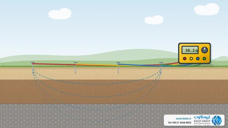
To reach the required resistance, first measure the soil resistivity (measuring soil resistivity), choose the shape and number of electrodes with the electrode resistance formulas, and match the material to the soil conditions (earth electrode materials): for example, a copper-bonded earth rod in an inspection pit, and in high-resistivity soil GIM ground improvement material. Make the connections with earth clamps or exothermic welding. We cover system earthing (the transformer neutral) in our article electrical earthing system specifications.
Steps for determining protective earthing system specifications
- System type and fault current: TN, TT or IT; the short-circuit current and the disconnection time of the protective device.
- Touch voltage limit: in low voltage, 50 V with the disconnection times of IEC 60364-4-41; in high voltage, according to EN 50522 or IEEE 80.
- Conductor cross-sections: protective, earthing and bonding conductors according to IEC 60364-5-54.
- Electrode and earth resistance: based on the soil resistivity and the required resistance.
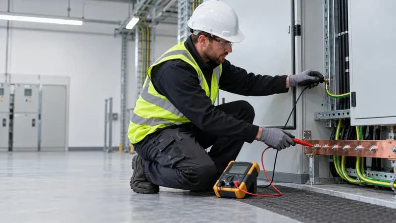
- Bonding and testing: bonding all metal parts, and after installation measuring earth resistance, continuity and fault loop impedance (measurement method).
We carry out earthing and bonding system design and earthing system testing and measurement. For advice, send our specialists the type of power system, the short-circuit current, the site drawing and the soil measurement results, or get in touch through the contact us page.