Short answer: Electrical earthing, which codes call "operational earthing", means connecting the neutral point of a transformer or generator to earth. This connection is part of the power circuit and carries short-circuit current during a fault, so its specifications cannot be set by one fixed figure. The work rests on three pieces of data: the neutral earthing method, the highest short-circuit current to earth and the trip time of the protective relay. From these three we get the earthing conductor cross-section, the required electrode resistance, and whether the substation's high voltage and low voltage earths are separate or shared.
At KALOT Group we explain this method in this guide in plain language and with examples. We cover the difference between electrical and protective earthing in the article What protective earthing and electrical earthing mean, and the protective side, meaning touch voltage and automatic disconnection, in the article Specifications of a protective earthing system.
What is electrical earthing (operational earthing)?
Under the Earthing System Safety Code (1401), operational earthing is the connection of the system's neutral point to earth; its job is to maintain the insulation and limit overvoltages. Protective earthing, by contrast, connects the metal frames of equipment to earth so that the faulty circuit disconnects quickly when a fault reaches the frame. In a substation the two usually meet at the main earth bar, and an earthing conductor carries them to the earth electrodes.
For this bar we offer an earth bar with a disconnect link; opening the link lets you isolate the electrode from the system for measurement. When several sources (several transformers or generators) run in parallel, the neutral is connected to the protective conductor and earth at one point only, so that circulating current does not flow in the protective conductors. BS 7430 recommends this, and the 1401 code also prohibits connecting each source's neutral directly to earth in multi-source systems, accepting this connection only at the main panel. See the types of earthing arrangement (TN, TT and IT) in the article Earthing and its types.
Methods of earthing a transformer's neutral point
The neutral earthing method has the greatest effect on the size and duration of the earth fault current, and through that it shapes the choice of insulation level, surge protective devices (SPDs), protective relays and the earthing system design. IEEE 142 compares the common methods as follows:
Method | Earth fault current | Protection response | Common application |
|---|---|---|---|
Direct (solid) earthing | High; with "effective earthing", at least 60 percent of the three-phase short-circuit current | Immediate disconnection by relay or fuse | Low voltage networks and many distribution networks |
Low-resistance earthing | 100 to 1000 A, usually 400 A | Fast, selective disconnection; the resistor is built for 10 or 30 seconds | Medium voltage networks up to 15 kV with large motors |
High-resistance earthing | Usually 10 A or less | Alarm without immediate disconnection; the resistor is built for continuous duty | Industries where a power cut at the first fault is costly |
Resonant earthing (coil) | The capacitive fault current is compensated and reduced by the coil | Depends on the network design | Some medium voltage networks |
Isolated neutral | Only a small capacitive current | Continued operation at the first fault | No longer recommended because of transient overvoltage during repeated faults |
In the low-resistance method, the neutral earthing resistance comes from R = Vln / Ig, where Vln is the phase-to-neutral voltage and Ig is the desired fault current. For example, in a 20 kV network (phase-to-neutral voltage about 11547 V) with a current of 400 A, a resistance of about 29 ohms is needed. In Iran, the 1401 code requires a TN-S or TN-C-S system at sites with a dedicated substation and one transformer. It prohibits the IT system in public distribution networks and requires it in certain special workplaces, together with an insulation monitoring device.
What data gives the specifications of an electrical earthing system?
According to EN 50522, the main design data for an earthing system in high voltage installations are the fault current value, the fault duration and the soil properties. The first two depend largely on the neutral earthing method:
- Highest short-circuit current to earth: three-phase-to-earth, two-phase-to-earth, single-phase-to-earth and double faults are examined inside and outside the substation to find the worst case. Allow for future growth of the network as well.
- Fault duration (relay and circuit breaker trip time): for designing substation earthing conductors, BS 7430 suggests 1 second for 400 and 275 kV networks and 3 seconds for lower voltages.
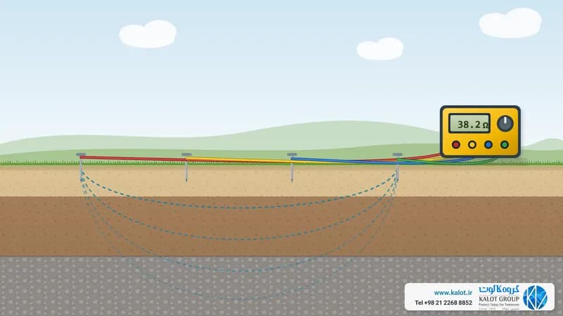
- Soil resistivity and substation layout: these must be measured on site (how to measure soil resistivity).
One important point: the current that heats the conductor is not the same as the current that raises the earth potential. In a substation with an earthed neutral, part of the fault current returns to the transformer through the neutral and the cable sheaths, and only the rest enters the soil. EN 50522 defines a separate current for each.
How do we calculate the earthing conductor cross-section?
The earthing conductor must carry the fault current for the fault duration without heating so much that it or its connections are damaged. For disconnection times up to 5 seconds, IEC 60364-5-54 gives this formula: S = √(I² t) / k, where S is the cross-section in square millimetres, I is the fault current in amperes, t is the fault duration in seconds and k is a factor that depends on the conductor material and the permitted temperature. For bare conductors, Table A.54.6 of this standard gives the factors as follows:
Conditions | Bare copper | Bare steel |
|---|---|---|
Visible and in restricted areas (final temperature 500 degrees for copper and steel) | 228 | 82 |
Normal conditions (final temperature 200 degrees) | 159 | 58 |
Fire risk (final temperature 150 degrees) | 138 | 50 |
Annex D of EN 50522 has a more precise method that enters the initial and final temperatures separately: A = (I / K) × √(t / ln((θf + β) / (θi + β))). For copper, K is 226 and β is 234.5; for steel, K is 78 and β is 202.
Example: suppose the earth fault current is 15 kA and the fault duration is 1 second. With the IEC method and k of 159, the required cross-section is 94.3 mm². With the EN 50522 method, bare copper, an initial temperature of 20 and a final temperature of 300 degrees, it is 77 mm². Both lead to the next standard size up, a 95 mm² bare copper conductor. If the same current lasts 3 seconds, the IEC method gives 163 mm², which means a 185 conductor. So the fault duration matters as much as the current itself.
The minimums must also be met, even if the calculation gives a smaller figure:
- IEC 60364-5-54: earthing conductor of at least 6 mm² copper or 50 mm² steel; aluminium is not permitted for the earthing conductor.
- EN 50522 in high voltage installations: at least 16 mm² copper, 35 aluminium or 50 steel.
- The 1401 code: the main earthing conductor from the electrode to the main earth bar must be copper and at least 35 mm²; aluminium, bare or copper-clad, must not be in contact with the soil.
Fault current usually divides between several paths, so each branch of the conductor can be designed for its own share. The withstand capacity of the connections, especially bolted ones, must be checked too. Instead of a conductor you can use copper tape with an equal or larger cross-section. Make the connections with exothermic welding or earthing clamps, because IEC 60364-5-54 does not accept a connection that relies on solder alone.
Earth resistance and earth potential rise (EPR)
When fault current enters the earthing system, the potential of all earthed parts rises relative to remote earth. This value is called the earth potential rise: EPR = IE × ZE, where IE is the current entering the soil and ZE is the impedance of the earthing system. For example, a current of 1000 A in a resistance of 1 ohm raises the substation's earth potential by 1000 V. The lower the earth resistance, the lower the EPR.
According to EN 50522, if the EPR is below the permissible touch voltage and the conditions for interconnecting the high and low voltage earths are also met, the design is complete. Otherwise, touch and step voltage inside and around the substation must be checked and corrective measures taken where needed. We give the permissible touch voltage limit in the article Specifications of a protective earthing system.
There is no fixed figure for neutral earth resistance, but several references give values. IEEE 142 considers a resistance below 1 ohm necessary only for large substations, and 1 to 5 ohms suitable for industrial substations and large commercial buildings. The 1401 code requires an electrode resistance of less than 2 ohms where the neutral and protective conductor separate in a TN-C-S system, and less than 1 ohm for a shared high and low voltage electrode.
To reach the required resistance, choose the shape and number of electrodes using the earth electrode resistance formulas: for example, a copper-bonded earth rod in a polyethylene earth pit for inspection, and in high-resistivity soil GIM ground improvement material.
High and low voltage earths in a substation: separate or shared?
During a fault on the high voltage side, part of the substation's EPR may transfer to the low voltage installation through the neutral and protective conductors. There are two approaches: interconnecting all the earths, or separating the high voltage earth from the low voltage earth.
- EN 50522: prefers interconnection wherever feasible; if the low voltage installation lies entirely within the high voltage earthing area, interconnection is mandatory. Otherwise, the 2010 edition of this standard sets conditions based on EPR. For example, in a TN system the EPR must not exceed F times the permissible touch voltage (F is usually 2), and for the stress voltage on low voltage equipment, the EPR is limited to 1200 V for faults shorter than 5 seconds and 250 V for longer faults. These criteria now appear in IEC 61936-1. When the earths are separated, a distance of 20 m has been widely used in networks below 50 kV.
- Earthing System Safety Code (1401): prohibits a shared earth for the substation's high voltage side and the transformer's low voltage side (Article 123). The two electrodes must be at least 20 m apart with no conductor connecting them; the low voltage electrode and neutral must also be at least 20 m from the substation structure, and the neutral must reach it by a non-metallic route (Articles 126 to 128). Only where two independent electrodes are not feasible is a shared electrode with a total resistance of 1 ohm at most accepted (Article 129). If a high voltage overhead line runs within 3 km of the substation, surge protective devices (SPDs) and two separate electrodes outside each other's voltage zone are required (Article 130).
For projects in Iran, take this code as your basis and coordinate with the network designer and the regional electricity operator.
Installing transformer neutral earthing in practice
BS 7430 gives several practical recommendations for substation earthing conductors, and they also match our experience:
- Run the main earth bar or conductor as a ring around the substation as far as possible, with short branches to each piece of equipment; in larger substations, reinforce the ring with several cross-connections.
- Bury bare copper or steel conductors at a depth of about 600 mm; copper tape in contact with galvanised steel should be tinned (tinned copper tape).
- Keep the connection of surge protective devices (SPDs) to earth short and direct, with enough cross-section, and do not route it through pipes or steel parts.
- Where a bare conductor passes under a metal fence with its own separate earth, insulate it for at least 2 m on each side of the fence.
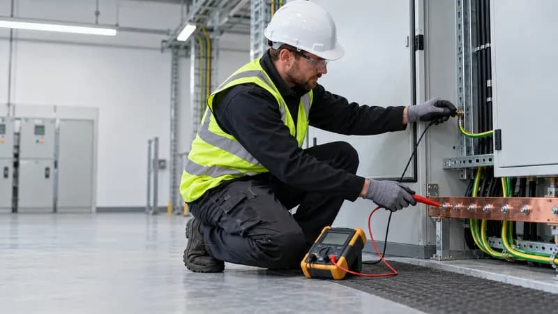
All connections must keep their low resistance even after fault current has passed through them many times; we offer earth bars, earthing clamps and exothermic welding for exactly this job. Do not forget to bond the metal parts of the substation too (bonding and equipotential bonding).
Steps for setting the specifications of an electrical earthing system
- Neutral earthing method: direct, low or high resistance, resonant or isolated, according to the network and the regulations.
- Fault current and duration: the highest short-circuit current to earth and the trip time of the relay and circuit breaker.
- Earthing conductor cross-section: using the IEC 60364-5-54 or EN 50522 formula, and at least the minimums set by the standards and the code.
- Soil, resistance and EPR: measure the soil resistivity, design the electrodes, and check the earth potential rise and touch voltage.
- High and low voltage earths, installation and testing: decide whether the earths are separate or shared, then install, measure earth resistance and continuity (measurement method) and document the work.
We provide earthing system design and consulting, earthing installation and earthing system testing and earth resistance measurement. For advice, send our specialists the transformer's voltage and power, the neutral earthing method, the short-circuit current and trip time, the substation drawing and your soil measurement results, or get in touch through our contact us page.