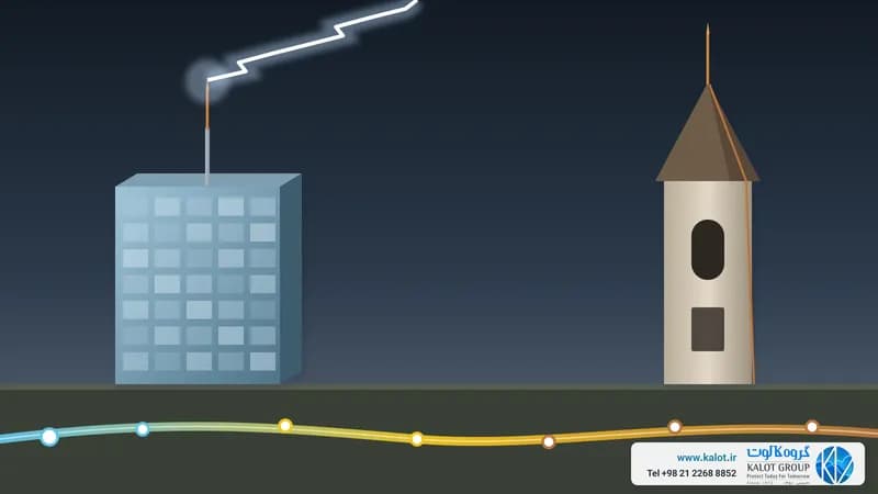
Short answer: NF C 17-102 is the French national standard for protecting buildings against direct lightning strikes with early streamer emission (ESE) air terminals, also called active lightning rods. The current edition dates from September 2011 and replaced the 1995 edition. It sets out how the air terminal is tested, how its protection radius is calculated, and how down conductors, earthing, bonding and inspection are carried out.
At KALOT Group we supply Franklin France ESE air terminals together with every component of the system. This guide explains the most important parts of the standard in plain language. For the installation points, clause by clause, see our article on 25 key points of NF C 17-102.
What Is NF C 17-102 and What Does It Cover?
NF C 17-102, titled “Lightning protection: early streamer emission lightning protection systems”, is published by AFNOR, the French standards body. It is based on the electrogeometric model of lightning, the same model behind the rolling sphere method. Spain has a near-identical standard, UNE 21186:2011.
The table of contents of the 2011 edition shows what the standard covers:
- Need for protection and system components: which buildings need protection and what the system is made of.
- ESE lightning protection system: design, air terminal, down conductors, equipotential bonding and separation distance.
- Earthing system: electrode types, additional measures, equipotential bonding, proximity to other installations and materials.
- Special measures: antennas, stores of explosive and flammable materials, and religious buildings.
- Installation file, inspection and maintenance.
- Annexes: risk assessment (Annex A), lightning density map (B), air terminal tests (C), protection of people against electric shock caused by lightning (D) and examples of the kc coefficient (E).
What Changed in the 2011 Edition?
According to an assessment by INERIS, the French national institute for industrial environment and risks, the main changes in the 2011 edition were:
- The ΔT measurement became stricter: a reference rod is tested alongside the air terminal, with new statistical criteria.
- ΔT was given a floor and a ceiling: below 10 µs a device does not count as ESE, and no more than 60 µs may be used in calculations.
- Endurance tests were added: 100 kA lightning current, salt mist and sulphurous atmosphere.
- Models with electronic circuits gained electromagnetic compatibility (EMC) requirements.
- Protection level IV was added, giving four levels as in IEC 62305.
- Component requirements were aligned with the European standards EN 50164 (now EN 62561) and EN 62305.
- A new section was added on checking the integrity of the air terminal (clause C.5).
What Is ΔT and How Is It Measured?
Every air terminal, conventional or ESE, attracts lightning by launching an upward leader from its tip. An ESE air terminal is built to launch that leader earlier than a simple rod of the same shape and height. This time gain is called ΔT and is expressed in microseconds. ΔT is measured in a high-voltage laboratory under Annex C of the standard: the air terminal and a reference rod are subjected in turn, under identical conditions, to a background electric field and an impulse wave, and the leader inception time of each is recorded.
Before going on sale, every ESE model must pass this group of Annex C tests:
- Identification, technical documents and product marking;
- Dimensional check and mechanical test;
- Environmental tests in salt mist and humid sulphurous atmosphere;
- 100 kA lightning current test;
- Impulse voltage test and, for electronic models, EMC;
- ΔT measurement alongside the reference rod.
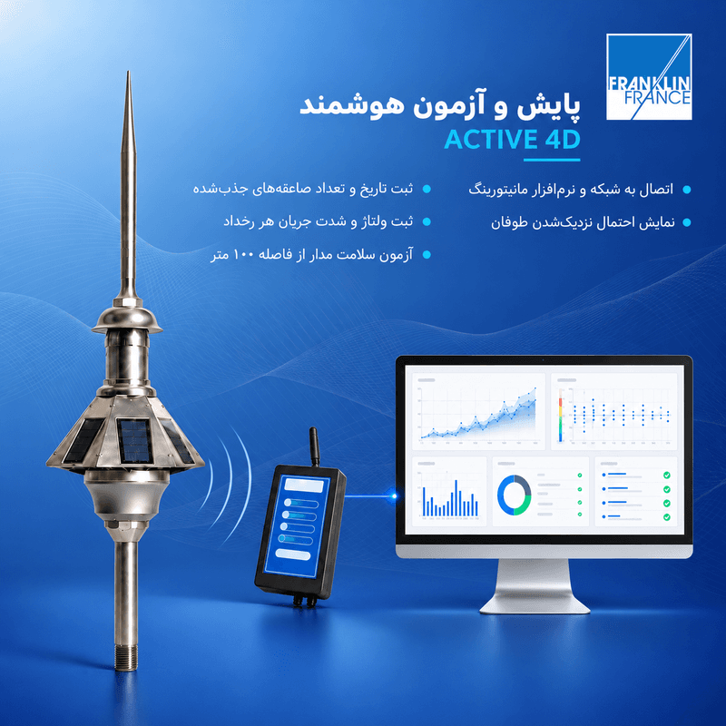
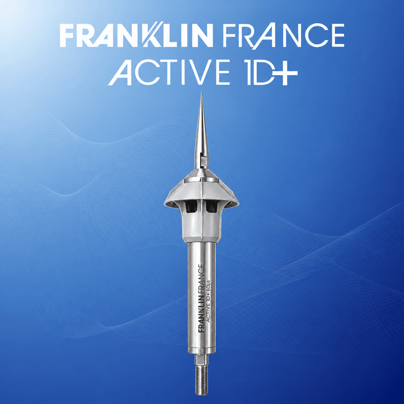
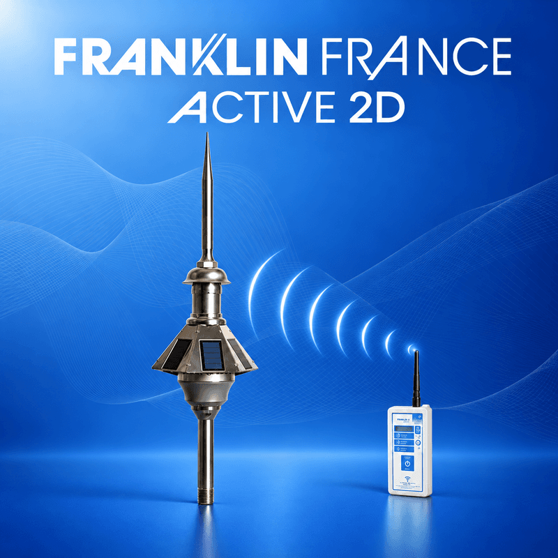
In design, ΔT becomes a gain in length: ΔL = ΔT × 1 m/µs, so each microsecond counts as one metre. When buying, ask for ΔT from the Annex C test report, not just the brochure. The air terminals we supply fall within this range: ACTIVE 1D+ with ΔT of 12, 25, 45 or 60 µs, and ACTIVE 2D and ACTIVE 4D with 30 or 60 µs.
How Is the Protection Level Chosen?
Before any calculation, you need to establish whether the building needs protection and at what protection level. This is done with the risk assessment in Annex A of the standard or the full method of IEC 62305-2, and it depends on lightning density in the area, the size and use of the building, its contents and the consequences of damage. The result is one of four levels, from I (the strictest) to IV. Each level has a value r used in the protection radius formula: 20 m for level I, 30 m for II, 45 m for III and 60 m for IV, the same as the rolling sphere radius in IEC 62305-3. Lightning risk assessment is one of our services.
How Is the Protection Radius of an ESE Air Terminal Calculated?
The protected zone of each ESE air terminal is expressed by its protection radius Rp. Rp is the radius of a circle on a horizontal plane, and h is the height of the terminal tip above that plane. The plane is taken through the furthest point that has to be protected. The standard formula for h of 5 m or more is:
Rp(h) = √( 2·r·h − h² + ΔL·(2·r + ΔL) )
For h between 2 and 5 m, Rp falls in proportion to height: Rp(h) = h × Rp(5) / 5. The minimum permitted h is 2 m. We calculated the table below with this formula for three common ΔT values (figures in metres):
Protection level (r) | ΔT | h = 2 m | h = 3 m | h = 4 m | h = 5 m | h = 6 m | h = 10 m | h = 20 m |
|---|---|---|---|---|---|---|---|---|
Level I (20 m) | 25 microseconds | 17 | 25 | 34 | 42 | 43 | 44 | 45 |
Level I (20 m) | 45 microseconds | 25 | 38 | 51 | 63 | 63 | 64 | 65 |
Level I (20 m) | 60 microseconds | 31 | 47 | 63 | 79 | 79 | 79 | 80 |
Level II (30 m) | 25 microseconds | 20 | 29 | 39 | 49 | 49 | 51 | 54 |
Level II (30 m) | 45 microseconds | 28 | 42 | 57 | 71 | 71 | 72 | 74 |
Level II (30 m) | 60 microseconds | 35 | 52 | 69 | 86 | 87 | 88 | 89 |
Level III (45 m) | 25 microseconds | 23 | 34 | 46 | 57 | 58 | 61 | 65 |
Level III (45 m) | 45 microseconds | 32 | 48 | 64 | 81 | 81 | 83 | 86 |
Level III (45 m) | 60 microseconds | 39 | 58 | 78 | 97 | 97 | 99 | 102 |
Level IV (60 m) | 25 microseconds | 26 | 39 | 52 | 65 | 66 | 69 | 75 |
Level IV (60 m) | 45 microseconds | 36 | 54 | 72 | 89 | 90 | 92 | 97 |
Level IV (60 m) | 60 microseconds | 43 | 64 | 85 | 107 | 107 | 109 | 113 |
An example: take a building with protection level II and an air terminal with ΔT of 45 µs, its tip 5 m above the roof. The protection radius on the roof is about 71 m. But if a point 10 m below the roof also has to be protected, h becomes 15 m and Rp on that plane is about 73 m. So a “protection radius” figure means nothing without ΔT, h and the protection level. The largest catalogue figure is usually for level IV at a great height.
In practice more than one air terminal is sometimes needed, for example when a roof is very large or parts of the building lie outside the radius of a single terminal. We also provide lightning protection system consulting and design.
What Are the Components of a Complete ESE System?
The air terminal is only the top of the system. Under the standard, a complete system includes:
Part | What it does and what the standard says | Suitable parts |
|---|---|---|
Air terminal | Highest point of the structure; at least 2 m above anything in the protected zone | |
Mast and base | Holds the terminal firmly at the required height | |
Down conductor | At least two routes per terminal, preferably on different façades; at least 50 mm² | |
Test joint and counter | To disconnect each conductor and measure its earth, and to record the number of strikes | |
Earthing system | One earth per down conductor, below 10 Ω and low inductance | Copperbond earth rod, earth inspection pit, KALweld® exothermic welding |
Bonding and SPDs | Bonding to the building earth and metal installations; SPDs at power and data entry points |
We explain bonding in our article on bonding and equipotential bonding, and SPDs in types of surge protective devices (SPD).
How Often Should an ESE Air Terminal Be Inspected?
Clause 8 of the standard deals with the installation file, inspection and maintenance. The intervals published by ESE manufacturers, citing the standard, are: for levels I and II, a visual inspection every year and a full inspection every 2 years; for levels III and IV, a visual inspection every 2 years and a full one every 4 years; and always after any recorded strike. In a full inspection, the test joint of each conductor is opened and its earth resistance measured separately. Under clause C.5, the ESE manufacturer must provide instructions for testing the integrity of the air terminal. For the models we supply, the remote tester does this test from the ground. We also carry out periodic testing and inspection.
Key Points in Brief
- ΔT is accepted only from an Annex C test report, and is capped at 60 µs in calculations.
- Calculate the protection radius for the real h and the project’s protection level, not from the largest catalogue figure.
- The terminal tip stands at least 2 m above anything in the protected zone.
- Each air terminal needs at least two down conductors, and each conductor an earth below 10 Ω.
- All earths are bonded to the building earth, and SPDs are needed too.
- Inspect periodically and after every strike, and test the integrity of the air terminal.
The full list of 25 points, with clause and figure numbers, is in our article on key points of NF C 17-102.
How Do NF C 17-102 and IEC 62305 Relate?
The international IEC 62305 series describes the conventional methods, namely the rolling sphere, protection angle and mesh, in IEC 62305-3, and does not include the ESE protection radius method. The 2011 edition of NF C 17-102 refers to those same European standards for risk assessment, protection levels and component requirements. So choose the air terminal under the standard the project specification calls for, and do all calculations under that same standard. We compare the two approaches impartially in our article on the difference between active and passive lightning rods, and list the standards in this field in lightning protection standards.
To choose a model, calculate the protection radius or get a quotation, send our specialists the building’s dimensions and drawings, its use and the standard the project requires, or reach us through our contact page.