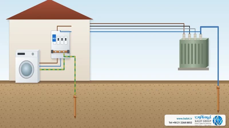
Short answer: TN-C is a system in which the transformer star point is earthed directly and the neutral and protective conductors are one shared conductor called PEN along the whole route. Equipment enclosures connect to this PEN. The system has one conductor fewer, but it comes with serious limitations: PEN is allowed only in fixed installations with enough cross-section, and a residual current device (RCD) does not work in it.
TN-C system structure
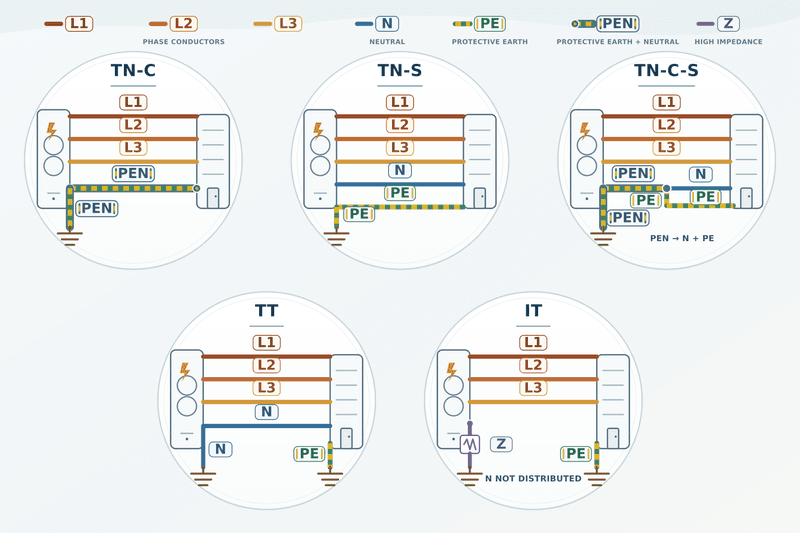
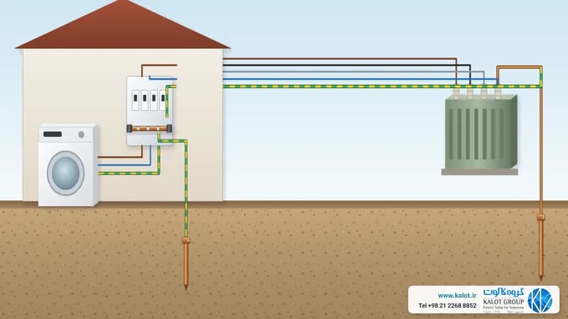
In TN-C, four conductors are run: three phases and PEN. Because PEN both carries neutral current and acts as the protective conductor, it carries current in normal operation and has a voltage drop along it, so enclosures connected to PEN always sit at a small voltage difference from earth. PEN is identified by green and yellow with blue marks at both ends, or by blue with green and yellow marks.
Standard conditions for the PEN conductor
- According to IEC 60364-5-54, PEN is allowed only in fixed installations, with a cross-section of at least 10 mm² copper or 16 mm² aluminium, so it has no place in ordinary socket wiring or flexible cords.
- PEN must never be interrupted: no switch, fuse or isolating device is allowed on it.
- According to IEC 60364-4-41 and Article 10 of the Earthing System Safety Regulation (1401), residual current devices are not used in TN-C.
Why doesn't a residual current device work in TN-C?
A residual current device measures the difference between outgoing and returning current. In TN-C, enclosure fault current returns through the same PEN that passed through the device, so it sees no difference and does not trip. Protection in TN-C comes only from a circuit breaker or fuse and the condition Zs × Ia ≤ U0.
The risk of a broken PEN
If PEN breaks, equipment enclosures after the break connect to the phase through the load and can become live at close to phase voltage, without any device disconnecting. That is why PEN is installed with a large cross-section, firm connections and repeated earthing along the network.
TN-C pros, cons and uses
- Advantage: one conductor fewer and lower cabling cost in distribution networks.
- Disadvantage: no protection from a residual current device, the risk of a broken PEN, and neutral current in the structure and pipes, which creates noise and corrosion. IEC 60364-4-44 recommends not using TN-C in buildings with information technology equipment (earthing and EMC).
- Use: mostly in distribution networks and older installations. In a modern building, the PEN splits into neutral and PE at the entrance and the system becomes TN-C-S.
Where TN-C sits among earthing systems
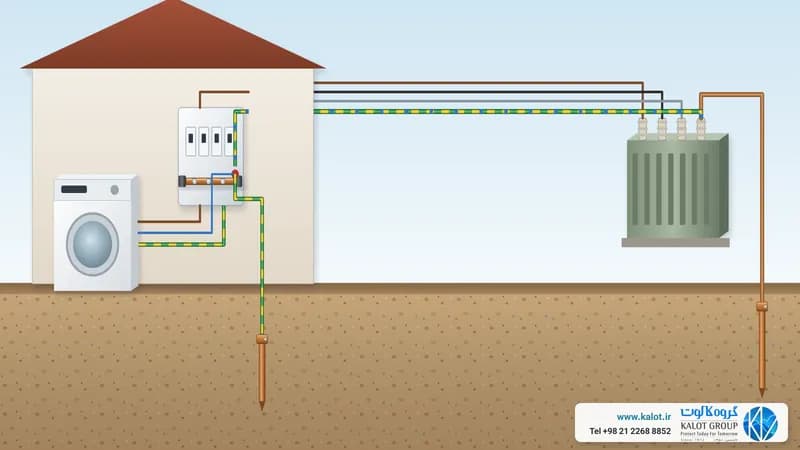
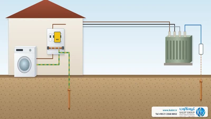
Each system's name has two or three letters. The first letter says how the source (the transformer star point) relates to earth: T means directly earthed, and I means isolated from earth or earthed through a high impedance. The second letter says where the metal enclosures of equipment connect: N means to the earthed point of the source through a protective conductor, and T means to the site's own earth electrode. A third letter appears only in the TN family: S means neutral and protective conductor are separate, and C means both share one conductor, called PEN.
System | Neutral and protective conductor | Protection against electric shock | Where you find it |
|---|---|---|---|
Separate from source to load | Circuit breaker or fuse, with Zs × Ia ≤ U0 | Factories and large buildings with their own substation | |
TN-C | One PEN conductor | Circuit breaker or fuse; a residual current device will not work | Distribution networks and older installations |
PEN up to the intake, then separate | Circuit breaker or fuse, plus a residual current device after the split point | Most buildings fed from the public network | |
Neutral from the network; protective conductor to the site electrode | Residual current device, with RA × IΔn ≤ 50 V | Buildings and installations far from the network or on a separate earth | |
Source isolated from earth; enclosures on the site electrode | Insulation monitoring for the first fault, disconnection on the second | Operating theatres, mines and industries where sudden loss of power is not acceptable |
For an overview, see types of earthing systems and what an earthing system is.
At KALOT Group we carry out earthing and bonding design and earthing system measurement and testing, and we offer the components, from copper-bonded earth rods and earth bars to green and yellow earth conductors and polyethylene inspection pits. To choose the right system, send our engineers your single-line diagram and supply type, or get in touch through our contact page.