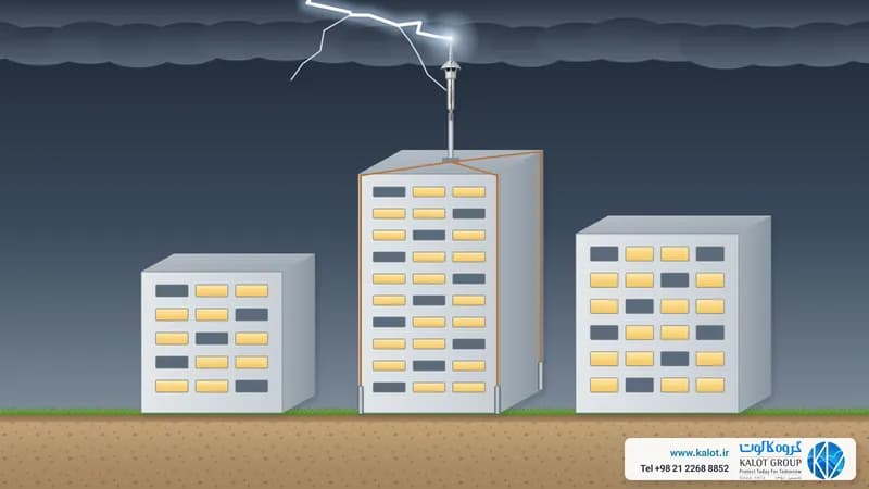
Short answer: to protect sensitive equipment such as servers, PLCs, telecoms and medical equipment from lightning and overvoltage, installing a surge protective device (SPD) alone is not enough. The IEC 62305-4 standard calls for four measures together: the earthing system, the bonding network, shielding and correct cable routing and coordinated SPDs. An SPD only works well when it has a short, low-impedance path to a common reference, and earthing and bonding are what create that reference.
Sensitive equipment can be damaged even by lightning that does not strike the building itself. The magnetic field of a nearby strike and overvoltage on incoming lines are enough to destroy electronic circuits (types of lightning effects). In this guide, we at KALOT Group explain these four measures in plain language.
The four IEC 62305-4 measures for sensitive equipment
- Earthing system: the path for lightning current into the soil. Ideally this is one integrated system, such as a foundation electrode and an earth ring around the building, not several separate earth pits.
- Bonding network: all metal parts, equipment enclosures and cable shields connect to one common reference, so no dangerous voltage difference appears between them during a strike (bonding and equipotential bonding).
- Shielding and cable routing: the building's metal structure, the equipment room shield, metal cable trays and shielded cables all weaken the lightning's magnetic field. Cables must also be routed so that they do not form a large loop.
- Coordinated SPDs: a Type 1 SPD at the building entrance, Type 2 at the distribution boards and Type 3 close to the sensitive equipment, all coordinated with one another (types of SPD). You need power SPDs for the power supply and data line SPDs for data and telecoms lines.
These measures are repeated at the boundary of each lightning protection zone (LPZ), so the overvoltage comes down step by step (lightning protection zones).
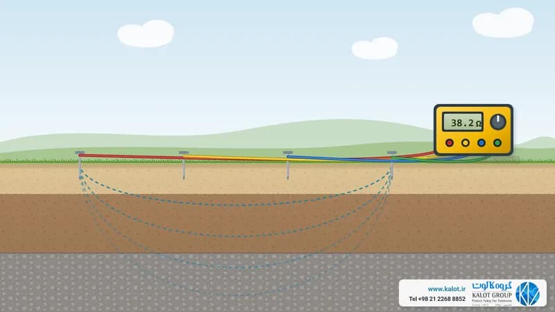
Earthing for sensitive equipment: impedance matters more than resistance
Lightning current peaks within a few microseconds. At that speed, the inductance of conductors matters far more than their ohmic resistance. The voltage across a conductor follows U = L · di/dt, so a long conductor, even with low resistance, builds up a high voltage across itself during a strike. That is why:
- Earthing and bonding paths should be short and direct, with an adequate cross-section, using copper tape and stable connections such as exothermic welding.
- One extensive, integrated earthing system, such as a foundation electrode and earth ring, performs better than a single earth pit.
- A separate, unbonded "clean" earth is not right for sensitive equipment. The potential difference between two separate earths during a strike can burn out the equipment (earthing and its types).
Keep SPD connecting wires short
The voltage reaching the equipment is the SPD's protection voltage plus the voltage across its connecting wires. IEC 60364-5-53 says the SPD connecting wires should be as short as possible, with a total length preferably no more than 0.5 m. A V-shaped connection, where the incoming line passes directly through the SPD terminal, and installing the SPD close to the bonding bar both reduce this extra voltage.
Equipment bonding network: star or meshed?
IEC 62305-4 sets out two main bonding arrangements for electronic systems:
- Star (single point): each piece of equipment connects to one common point through one conductor. This suits small, compact systems, provided all cables enter at that same point.
- Meshed: equipment connects through several short links to a meshed network, such as a copper grid under a raised floor or the metal structure. This suits extensive systems such as data centres and control rooms better, because it has low impedance at high frequencies.
For lightning protection, the shields of cables running between buildings or zones are bonded at both ends. Install bonding conductors using green and yellow earth wire and earth clamps. The cross-sections of protective and bonding conductors are given in IEC 60364-5-54. We also explain the difference between protective earth and functional earth for equipment in our article on protective earth and electrical earth.
Checklist for protecting sensitive equipment
Part | What to check |
|---|---|
Earthing system | Integrated, with an earth ring or foundation electrode; no separate, unbonded earth |
Bonding | All pipes, trays, enclosures and shields to a common bar; a meshed network for extensive systems |
Shielding and cable routing | Bonded metal trays, separation of power and data cables, avoiding large loops |
SPDs | Coordinated Type 1, 2 and 3; SPDs for data and telecoms lines; short connecting wires |
Test | Bonding continuity, earth resistance and SPD condition at periodic inspection |
We carry out surge protection design, earthing and bonding design and lightning risk assessment. For advice, send our specialists the building drawing, the routes of the power and data lines and a list of the sensitive equipment, or reach us through our contact page.