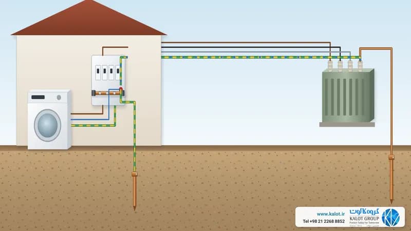
Earthing Systems Comparison Table (IEC 60364)
System | Layout | Neutral and earth | Behaviour under fault | Advantages | Disadvantages | Typical applications |
|---|---|---|---|---|---|---|
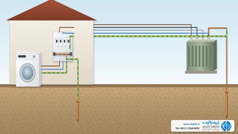
TN-S | L1/L2/L3 + N and PE, separate from the source | Transformer neutral earthed; separate PE to the load | Fast disconnection by protective devices; controlled touch voltage | High safety, better noise and EMC performance, easy fault-finding | Higher cable cost; PE needs maintenance | Modern buildings, offices, industry and sensitive sites |
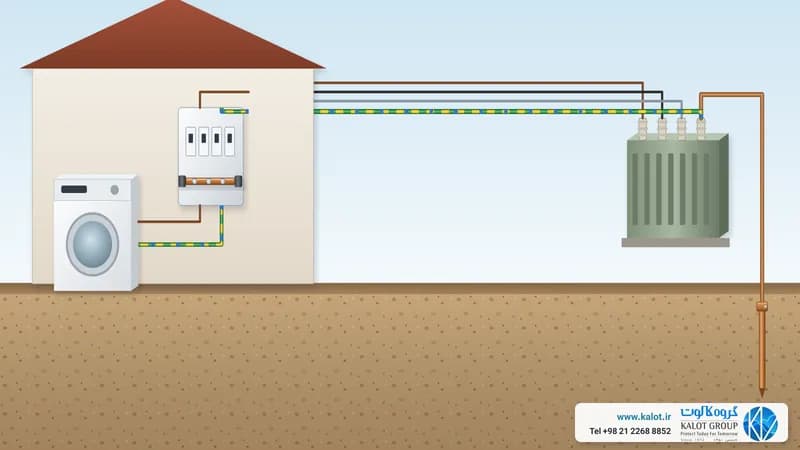
TN-C | L1/L2/L3 + PEN (neutral and earth combined) | Neutral earthed; one shared conductor to the load | A broken PEN is very dangerous; high voltage on metal enclosures | Low cost and simple cabling | Lower safety, more noise, prohibited or unsuitable in sensitive locations | Older networks and very low-budget projects |
TN-C-S | PEN first; split into N and PE near the load | Neutral earthed; separation at the point of use | Balances cost and safety, but a broken PEN before the split is high risk | Moderate cost; older networks can be upgraded | More noise than TN-S; the split point needs careful design | Urban distribution, residential complexes and network renewal |
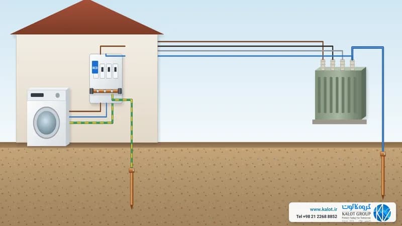
TT | Each consumer has its own independent local earth electrode | Transformer neutral earthed; consumer earth is independent | Fault current limited by electrode resistance; RCDs are essential | Good safety at the consumer, isolated from network faults | Higher earth resistance; periodic testing needed | Rural and scattered areas, stand-alone buildings |
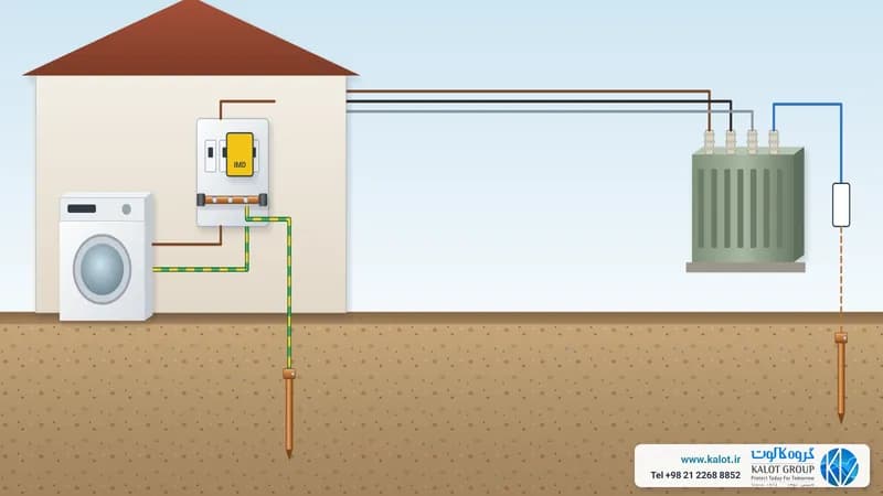
IT | Neutral unearthed or earthed through high impedance; equipment on a local earth | Neutral isolated or earthed through Z; local PE | First fault does not interrupt supply; second fault is dangerous | Excellent continuity of supply, suited to critical environments | More complex and costly; requires an IMD | Hospitals, operating theatres, critical industry and some data centres |
Summary and Quick Selection Guide
- Safest general standard: TN-S (where budget and infrastructure allow).
- Cost and safety balance on urban networks: TN-C-S (with a properly designed split point and supplementary earths).
- Older or low-cost networks: TN-C only in specific conditions, and never in sensitive locations.
- Scattered areas and stand-alone buildings: TT with RCDs and periodic earth resistance testing.
- No interruption at the first fault: IT with an IMD for continuous insulation monitoring.
EMC and noise: TN-S performs best and TN-C worst.
Maintenance: TT and IT need more regular measurement and monitoring (R, IMD).
Standards compliance: check the design against IEC 60364, and against IEC 62305 for lightning and surges.