
Earthing system installation guide with GIM®
Installation instructions: horizontal electrode in a trench with GIM®
Installation instructions: vertical earth rod electrode in the ground with GIM®
Installation instructions: plate electrode in the ground with GIM®
Review version: Draft 1 (awaiting technical approval), 24 September 2026. Items that need technical review are marked with an asterisk or a note in the drawings and under the tables.
GIM® installation guide
Mixing instructions and three installation methods for GIM® ground improvement material: horizontal trench, earth rod and copper earth plate. You can print each method separately.
Preparing the GIM® mix
Mix each bag of GIM with 8 litres of treated water and 2 kg of cement.
- Add nothing to the mix other than water and cement.
- While preparing the mix, keep soil, sand, plastic and pieces of the bag out of it.
- GIM and GIM Light are installed the same way and with the same mixing ratio. These instructions do not apply to ECO GIM, which is installed differently.
Method 1: horizontal trench with bare copper conductor or copper tape
Installation instructions: horizontal electrode in a trench with GIM®
1. Application
The earth conductor (bare copper conductor or copper tape) is laid horizontally in the trench and embedded in the GIM mix from below and above.
3. Execution drawing: final cross-section
Swipe the drawing left and right to see all dimensions.
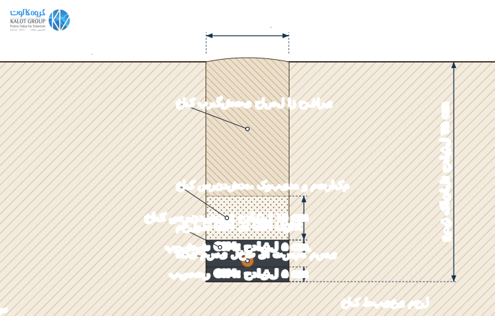
2. Installation stepsDetailed drawing
Step 1: Excavate a trench at least 10 cm wide and at least 75 cm deep. Where the local frost depth is greater, check the right depth for the site.
Step 2: Cover the trench floor with at least 5 cm of GIM mix.
Step 3: Lay the bare copper conductor or copper tape on the GIM bed.
Step 4: Cover the conductor with at least 5 cm of GIM mix; the whole surface of the conductor must be in full contact with the mix.
Step 5: Cover the GIM with at least 15 cm of screened soil, then tamp and compact it.
Step 6: Fill the rest of the trench completely with the excavated soil.
4. Consumption table
In each cell, the upper number is the trench length (cm), exactly as in the brochure. The lower number is the geometric volume of the same cross-section and length (width × height × length ÷ 1000), in litres; this number is calculated and does not appear in the brochure.
| Trench width (cm) | GIM height (cm) | ||||
|---|---|---|---|---|---|
| 5 * | 10 | 15 | 20 | 25 | |
| 10 | 37818.90 litres | 18918.90 litres | 12618.90 litres | 9418.80 litres | 7619.00 litres |
| 15 | 25218.90 litres | 12618.90 litres | 8418.90 litres | 6318.90 litres | 5018.75 litres |
| 20 | 18918.90 litres | 9418.80 litres | 6318.90 litres | 4718.80 litres | 3819.00 litres |
| 25 | 15118.88 litres | 7619.00 litres | 5018.75 litres | 3819.00 litres | 3018.75 litres |
| 30 | 12618.90 litres | 6318.90 litres | 4218.90 litres | 3118.60 litres | 2518.75 litres |
| 35 | 10818.90 litres | 5418.90 litres | 3618.90 litres | 2718.90 litres | 2219.25 litres |
| 40 | 9418.80 litres | 4718.80 litres | 3118.60 litres | 2419.20 litres | 1919.00 litres |
5. Notes and technical limits
* Needs technical review: The 5 cm height column is not valid for a full installation of this method: the instructions call for at least 5 cm of GIM below the conductor and 5 cm above it. Do not use this column until a technical decision is made.
Each number is the trench length (cm) that one bag fills at the given width and height.
Geometric volume: The geometric volume is calculated only from the dimensions and the printed length of each cell. That each bag fills about 19 litres follows from the brochure figures themselves and is not a tested yield of the mortar after mixing.
Table source: GIM brochure, 15 kg bag. The figures are quoted exactly from the brochure and are not an engineering calculation of the bag count.
Method 2: earth rod
Installation instructions: vertical earth rod electrode in the ground with GIM®
1. Application
The earth rod is set vertically in a hole and the space around it is filled with GIM mix up to the top of the earth rod.
3. Execution drawing: final cross-section
Swipe the drawing left and right to see all dimensions.
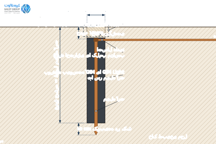
2. Installation stepsDetailed drawing
Step 1: Make a hole at least 15 cm in diameter and as deep as the earth rod is long.
Step 2: Place the earth rod in the hole and, where possible, drive it 15 cm into the floor so that its top sits about 15 cm below ground level. At the same stage, connect the earth conductor or tape to the earth rod with exothermic welding or a suitable clamp.
Step 3: Pour the GIM mix around the earth rod and compact it until the rod is fully covered all round and up to its top.
Step 4: Fill the rest of the hole with the excavated soil. Where the project needs it, use a dedicated access chamber for later access.
4. The KALOT polymer chamber
Two real photos of the chamber from outside and inside, and beside them a conceptual cutaway of the same chamber to show the approximate conductor route.
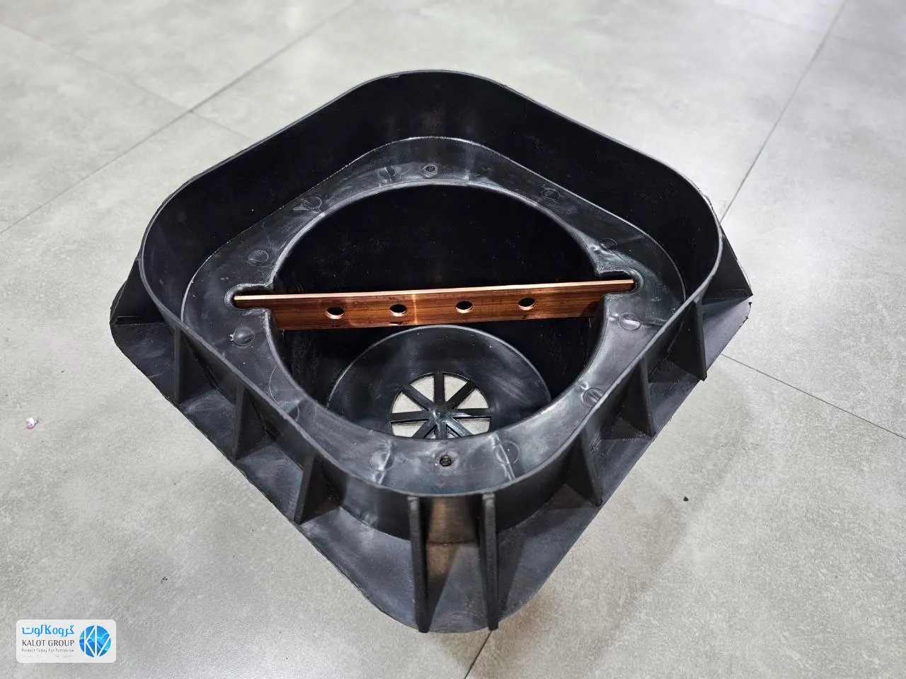
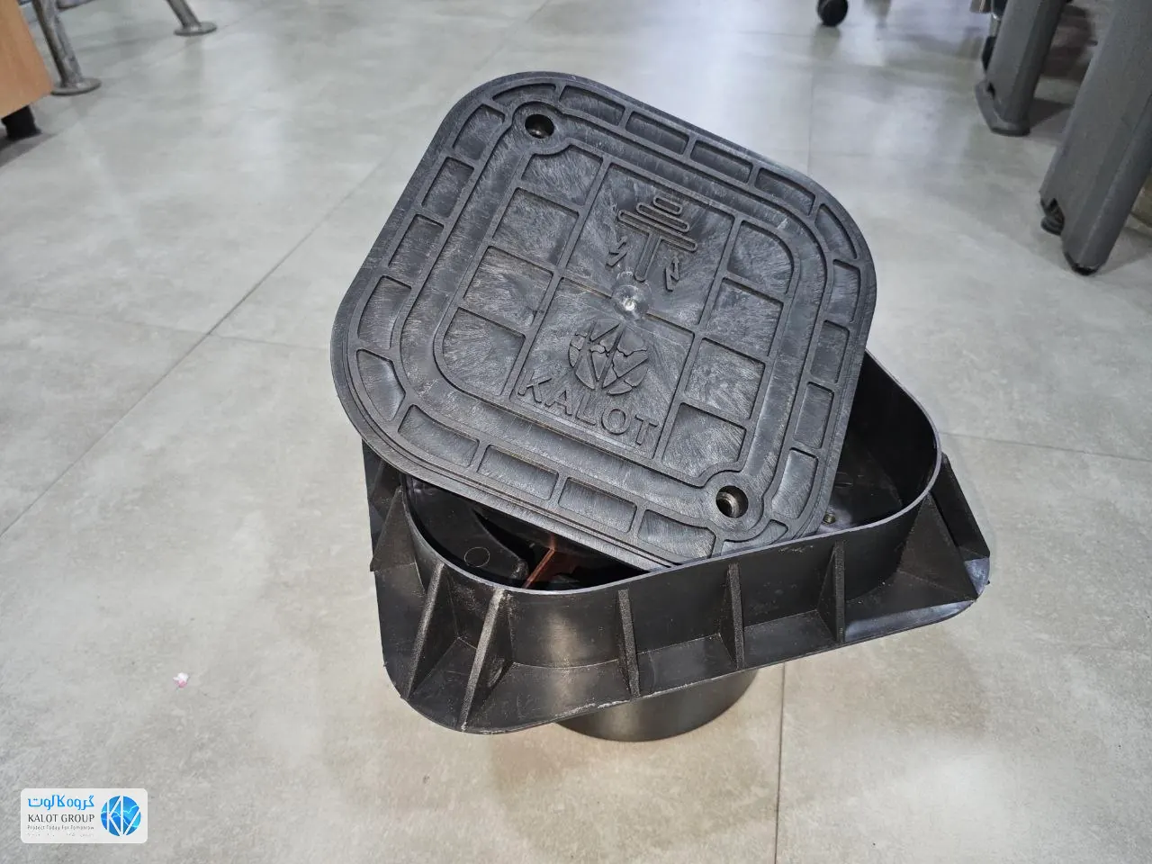
The photos only show what the chamber looks like; no size, hole spacing, clamp type or electrical rating should be read from them.
Swipe the picture left and right to see the drawing and its labels.
5. Consumption table
In each cell, the upper number is the bag count, exactly as in the brochure. The lower number is the gross geometric volume of a cylindrical hole of the same diameter and depth (area of a circle of that diameter × depth), in litres; this number is calculated and does not appear in the brochure.
| Hole diameter (cm) | Hole depth (m) | ||||||
|---|---|---|---|---|---|---|---|
| 1.2 | 1.5 | 2 | 2.5 | 3 | 4.5 | 6 | |
| 10 * | 19.42 litres | 111.78 litres | 115.71 litres | 119.63 litres | 123.56 litres | 235.34 litres | 247.12 litres |
| 15 | 121.21 litres | 126.51 litres | 235.34 litres | 244.18 litres | 353.01 litres | 479.52 litres | 6106.03 litres |
| 20 | 237.70 litres | 247.12 litres | 362.83 litres | 478.54 litres | 594.25 litres | 7141.37 litres | 10188.50 litres |
| 25 | 358.90 litres | 473.63 litres | 598.17 litres | 6122.72 litres | 8147.26 litres | 12220.89 litres | 16294.52 litres |
| 30 | 484.82 litres | 6106.03 litres | 7141.37 litres | 9176.71 litres | 11212.06 litres | 17318.09 litres | 22424.12 litres |
| 35 | 6115.45 litres | 8144.32 litres | 10192.42 litres | 13240.53 litres | 15288.63 litres | 23432.95 litres | 31577.27 litres |
| 40 | 8150.80 litres | 10188.50 litres | 13251.33 litres | 17314.16 litres | 20376.99 litres | 30565.49 litres | 40753.98 litres |
6. Notes and technical limits
* Needs technical review: The 10 cm diameter row is quoted from the brochure, but it is smaller than the minimum hole diameter of this method (15 cm) and is not a valid installation option.
In many cells the bag count of this table is lower than the geometric volume of the hole; for example, a hole 15 cm in diameter and 1.5 m deep holds about 26.51 litres, while the table shows one bag. These numbers are brochure estimates and are not a final order quantity until technical review.
Geometric volume: This is the gross geometric volume of the hole; it does not account for the volume of the earth rod itself, the share of backfill soil, the chamber height, the empty space above the top of the earth rod or the yield of the mortar after mixing. So the actual volume of GIM mortar or the number of bags needed cannot be derived from it, and the bag counts remain the brochure figures.
Table source: GIM brochure, 15 kg bag. The figures are quoted exactly from the brochure and are not an engineering calculation of the bag count.
Method 3: copper earth plate
Installation instructions: plate electrode in the ground with GIM®
1. Application
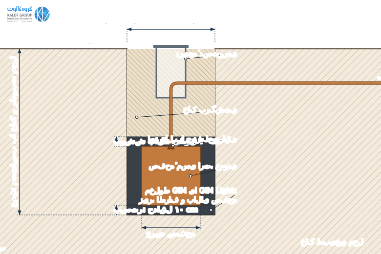
The copper earth plate is set vertically in a pit and covered with GIM mix below, around and above.
3. Execution drawing: final cross-section
Swipe the drawing left and right to see all dimensions.
2. Installation stepsDetailed drawing
Step 1: Excavate a pit whose diameter is 30 cm greater than the plate width. Set the depth to suit the soil and moisture conditions of the site. Connect the copper conductor or tape to the plate by exothermic welding at one point at least.
Step 2: Cover the pit floor with at least 10 cm of GIM mix.
Step 3: Set the plate vertically in the pit. (The brochure mentions a north to south alignment for the plate; this orientation is pending technical approval before it is presented as a general requirement.)
Step 4: Pour the GIM mix to at least 10 cm above the plate edge so that the plate is fully covered.
Step 5: If needed, install the access chamber and fill the rest of the pit with soil. (For the chamber, the brochure gives the phrase "50 cm below ground level"; its exact position and depth are not final until technical approval and are not dimensioned in the drawing.)
4. Consumption table
In each cell, the upper number is the bag count, exactly as in the brochure. The lower number is the gross geometric volume of the cylindrical part of the hole at that column's GIM height (area of a circle of that diameter × height), in litres; this number is calculated and does not appear in the brochure.
| Hole diameter (cm) | Largest plate width (cm) | GIM height (cm) | ||||||
|---|---|---|---|---|---|---|---|---|
| 20 * | 30 * | 70 | 80 | 90 | 100 | 120 | ||
| Largest plate height (cm) | - | 10 | 50 | 60 | 70 | 80 | 100 | |
| 60 | 30 | 356.55 litres | 484.82 litres | 10197.92 litres | 12226.19 litres | 13254.47 litres | 15282.74 litres | 18339.29 litres |
| 70 | 40 | 476.97 litres | 6115.45 litres | 14269.39 litres | 16307.88 litres | 18346.36 litres | 20384.85 litres | 24461.81 litres |
| 80 | 50 | 5100.53 litres | 8150.80 litres | 19351.86 litres | 21402.12 litres | 24452.39 litres | 27502.65 litres | 32603.19 litres |
| 90 | 60 | 7127.23 litres | 10190.85 litres | 24445.32 litres | 27508.94 litres | 30572.56 litres | 34636.17 litres | 40763.41 litres |
| 100 | 70 | 8157.08 litres | 12235.62 litres | 29549.78 litres | 33628.32 litres | 37706.86 litres | 42785.40 litres | 50942.48 litres |
| 110 | 80 | 10190.07 litres | 15285.10 litres | 35665.23 litres | 40760.27 litres | 45855.30 litres | 50950.33 litres | 601140.40 litres |
| 120 | 90 | 12226.19 litres | 18339.29 litres | 42791.68 litres | 48904.78 litres | 541017.88 litres | 601130.97 litres | 721357.17 litres |
5. Notes and technical limits
* Needs technical review: No plate fits in the 20 cm column, and the 30 cm column only suits a plate up to 10 cm high; these two columns need technical review.
The bag count is not final without the actual plate dimensions: the hole diameter must be at least "plate width + 30 cm", and the GIM height must cover at least 10 cm below the plate, the plate height itself and 10 cm above it.
The "largest plate width/height" column and row are not in the brochure; they are derived only from these two brochure conditions, so that an invalid combination is easier to spot.
In some cells the bag count is estimated lower than the geometric volume of the hole; these numbers are brochure estimates and are not a final order quantity until technical review.
Geometric volume: This is the gross geometric volume of the cylindrical part; it does not account for the volume of the plate and conductor, the share of backfill soil, the chamber height or the yield of the mortar after mixing. So the actual volume of GIM mortar or the number of bags needed cannot be derived from it, and the bag counts remain the brochure figures.
Table source: GIM brochure, 15 kg bag. The figures are quoted exactly from the brochure and are not an engineering calculation of the bag count.